Building material compression resistance comparison detection device

A detection device and anti-pressure technology, which is applied in the direction of measuring device, using stable tension/pressure to test the strength of materials, analyzing materials, etc., can solve the cumbersome testing process and the inability to simultaneously detect intuitive observation and understand the strength comparison of different building materials, etc. problem, achieve the effect of intuitive experimental results and improve practicability

Active Publication Date: 2020-08-21
GUIZHOU BUILDING MATERIAL QUALITY SUPERVISION TESTING INST
View PDF11 Cites 1 Cited by
  • Summary
  • Abstract
  • Description
  • Claims
  • Application Information

AI Technical Summary

Problems solved by technology

[0003]Current building materials need to test the strength of building materials before they are processed and used to determine whether they meet the construction requirements, but the general building material strength testing device only It can be tested separately, but cannot be tested at the same time. Intuitive observation and understanding of the strength comparison of different building materials, the test process is cumbersome, and the test results need to be re-compared

Method used


Image

  • Building material compression resistance comparison detection device
  • Building material compression resistance comparison detection device
  • Building material compression resistance comparison detection device

Examples


Embodiment 1

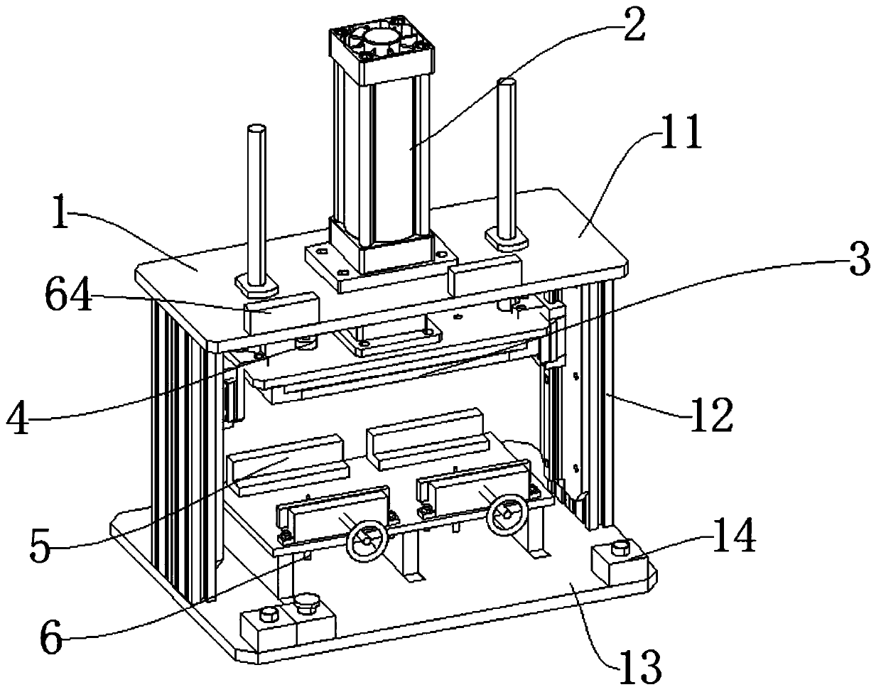
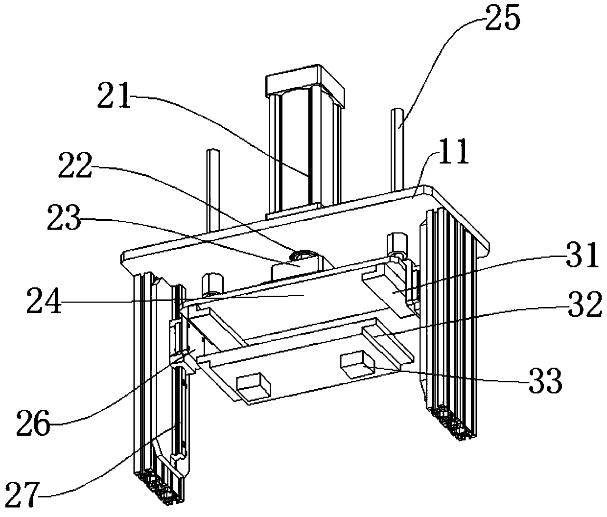
[0041] like Figure 1-Figure 6 As shown, the connecting mechanism 4 includes a first lock bar 41, a lifting plate 42, a fixed seat 43, and a first limit ring 44. The fixed seat 43 is connected to the upper end of the lifting seat 24 of the pressurizing mechanism 2, and the inner side of the fixed seat 43 is provided with a second A lock bar 41, the first lock bar 41 one end is connected with lifting plate 42, the first lock bar 41 other end passes through the lifting seat 24 of pressurizing mechanism 2 and connects the impact plate 32 of impact mechanism 3, the first lock bar 41 and fixed A first stop ring 44 is provided between the seats 43, a first return spring 45 is provided at the lower end of the first stop ring 44, and a first lock groove 46 is provided between the first lock bar 41 and the impact mechanism 3, when it needs to be replaced When the first impact head 33 or the second impact head 34, the first lock bar 41 is lifted, the first lock bar 41 is separated from ...

Embodiment 2

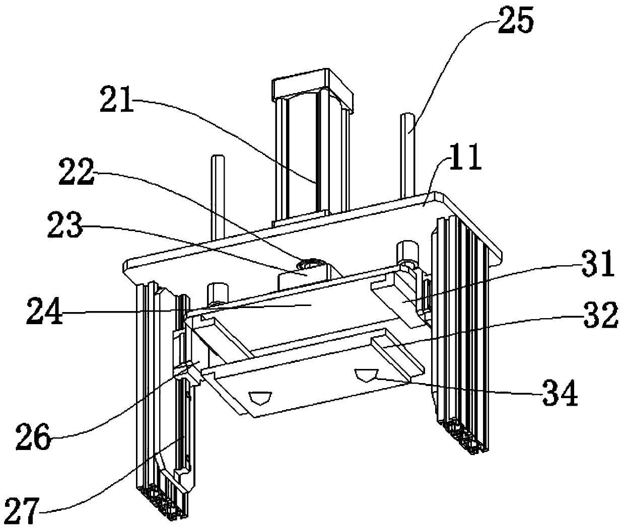
[0044] like Figure 7 The difference between this embodiment and Embodiment 1 is that the connecting mechanism 4 includes a second locking lever 411, a second limit ring 412, a second return spring 413, and a second locking groove 414, and the second locking lever 411 is arranged on the impact mechanism 3, a second lock groove 414 is provided between the second lock bar 411 and the lifting seat 24 of the pressurizing mechanism 2, and a second stop ring 412 is provided on the second lock bar 411. The second stop ring 412 A second return spring 413 is arranged between the ring 412 and the impact mechanism 3. When the impact plate 32 needs to be replaced, the impact plate 32 is pulled, and the second locking lever 411 retracts into the inner side of the impact plate 32. After replacement, the second locking lever 411 is locked. into the inner side of the second locking groove 414.


PUM


Abstract

The invention discloses a building material compression resistance comparison detection device. The device comprises a supporting mechanism used for supporting, a pressurizing mechanism used for providing a pressure, and a fixing mechanism used for fixing a to-be-tested building material. The pressurizing mechanism is connected to the upper end of the supporting mechanism, a power end of the pressurizing mechanism is connected with an impact mechanism, a connecting mechanism is arranged on the impact mechanism, the fixing mechanism is arranged on the lower side of the impact mechanism, and a detecting mechanism is arranged on the inner side of the fixing mechanism. The pressurizing mechanism cooperates with the impact mechanism, so that the impact speed and the impact mode of the impact mechanism can be changed and thus the practicability of the device is improved; the fixing mechanism and the detection mechanism are matched, two building materials can be detected at the same time; theto-be-detected building material is effectively fixed; deformation is accurately detected through a resistance strip, and the experiment result is more visual.

Description

technical field [0001] The invention relates to the field of building material testing, in particular to a building material anti-pressure contrast testing device. Background technique [0002] The building material industry is an important material industry in China. Building materials products include building materials and products, non-metallic minerals and products, and inorganic non-metallic new materials, which are widely used in construction, military industry, environmental protection, high-tech industries and people's lives. Features: 1. High strength and good durability. It is mainly reflected in the materials used as the stress components and structures of buildings. Such as the material used in beams, slabs, frames, etc. 2. High strength, good durability, good heat insulation, sound insulation and energy saving performance. It is mainly reflected in the materials used for the building envelope, such as the materials used in walls, doors, windows, roofs and o...

Claims


Application Information

Patent Timeline
Patent Type & Authority Applications(China)
IPC IPC(8): G01N3/02G01N3/12G01N3/307
CPCG01N3/02G01N3/12G01N3/307
Inventor 段舒熊莎熊易陶琳杨奎武
Owner GUIZHOU BUILDING MATERIAL QUALITY SUPERVISION TESTING INST
Why Eureka
Try Eureka