
Micro-joint type grating pinch plate, combined array and production method of micro-joint type grating pinch plate

A pinch plate and grating technology, applied in the direction of diffraction grating, optics, optical components, etc., can solve problems such as deviation of grating cylinder mirror line effect, prevent color change, improve integrity and accuracy of splicing effect, and reduce pre-investment cost Effect

Pending Publication Date: 2020-08-21
GUANGDONG SHENGQI TECH INC
View PDF9 Cites 0 Cited by
  • Summary
  • Abstract
  • Description
  • Claims
  • Application Information

AI Technical Summary

Problems solved by technology

[0002] At present, most of the grating images use the structure of a single grating plate as a way to display 3D light and shadow images. However, due to equipment limitations, the grating cylinder lens layer is mostly limited to regular shapes such as rectangles and circles, and large-area grating cylinders are being produced. When the mirror layer is used, there will be a phenomenon that the effect of the grating cylinder mirror line formed by embossing will be deviated; and through the splicing of multiple grating plates, it is necessary to consider that when splicing, two adjacent grating plates are likely to be spliced. Interfering with each other and affecting the overall visual effect

Method used


Image

  • Micro-joint type grating pinch plate, combined array and production method of micro-joint type grating pinch plate
  • Micro-joint type grating pinch plate, combined array and production method of micro-joint type grating pinch plate
  • Micro-joint type grating pinch plate, combined array and production method of micro-joint type grating pinch plate

Examples


Embodiment Construction

[0028] In order to enable the review committee to have a further understanding of the purpose, features and functions of the present invention, the preferred embodiments are hereby given in detail in conjunction with the drawings as follows:

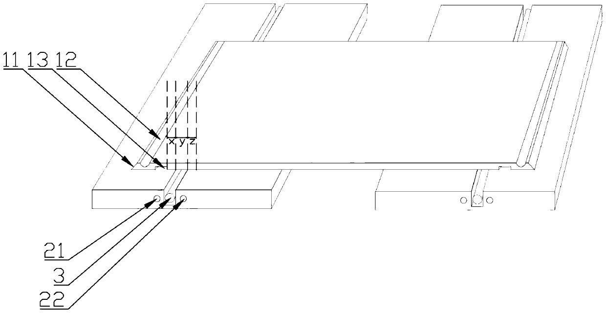
[0029] Such as Figure 1-6 The manufacturing method of the micro-seamed grating gusset shown is made through the following steps:

[0030] (1) Panel production: such as figure 1 As shown, firstly, the thickness is 3-5mm, the line density is 30-50 lines / inch, and the area is 0.5-1.5m 2 Conventional PS or PP material rectangular grating plate (keep two as much as possible), through the existing technology, pre-print the printing layer on the upper surface with ordinary UV ink or heat-resistant UV ink, and make the lenticular grating area on the lower surface , forming a rectangular grating plate with a 3D light and shadow effect that the viewer can feel through the observation of the lower surface; on a pair of opposite edges of the rect...


PUM


Abstract

The invention discloses a micro-joint type grating pinch plate. The pinch plate is integrally formed, wherein the upper surface of the pinch plate is provided with a printed layer, the lower surface of the pinch plate is provided with a lenticular grating area, two opposite sides of the pinch plate are vertically bent upwards to form mutually symmetrical insertion parts, the lower side of the outer edge of the pinch plate is a right-angled folded edge, inner channels are arranged on the inner side surfaces of the upper parts of the insertion parts, and outer channels are arranged above the lower parts of the insertion parts and the right-angled folded edge; the thickness of the pinch plate ranges from 3mm to 5mm, the linear density of the lenticular grating parallel to the right-angle folded edge ranges from 30 lines per inch to 50 lines per inch, and the deviation value between the height of the right-angle folded edge and the thickness of the pinch plate is + / -0.5mm. The machining process is simple, the grating plate is manufactured through existing grating picture machining equipment and machining method, softening and bending treatment is conducted on the plate, the manufactured grating pinch plate can form a grating plate combined array with micro joints and uniform vision through combination, and the grating pinch plate can be suitable for large-area 3D light and shadow image display.

Description

technical field [0001] The invention relates to the field of production methods of grating products, in particular to a micro-seam type grating buckle plate, a combination array and a production method thereof. Background technique [0002] At present, most of the grating images use the structure of a single grating plate as a way to display 3D light and shadow images. However, due to equipment limitations, the grating cylinder lens layer is mostly limited to regular shapes such as rectangles and circles, and large-area grating cylinders are being produced. When the mirror layer is used, there will be a phenomenon that the effect of the grating cylinder mirror line formed by embossing will be deviated; and through the splicing of multiple grating plates, it is necessary to consider that when splicing, two adjacent grating plates are likely to be spliced. Interfere with each other and affect the overall visual effect. Contents of the invention [0003] The object of the pr...

Claims


Application Information

Patent Timeline
Patent Type & Authority Applications(China)
IPC IPC(8): G02B5/18G02B30/30
CPCG02B5/1814G02B5/1847
Inventor 陈坤盛
Owner GUANGDONG SHENGQI TECH INC
Learn More