[0035] Example embodiments will now be described more fully with reference to the accompanying drawings. However, the example embodiments can be implemented in various forms, and should not be construed as being limited to the examples set forth herein; on the contrary, the provision of these embodiments makes the present disclosure more comprehensive and complete, and fully conveys the concept of the example embodiments To those skilled in the art. The drawings are only schematic illustrations of the present disclosure and are not necessarily drawn to scale. The same reference numerals in the figures indicate the same or similar parts, and thus their repeated description will be omitted.
[0036] In addition, the described features, structures, or characteristics can be combined in one or more embodiments in any suitable manner. In the following description, many specific details are provided to give a sufficient understanding of the embodiments of the present disclosure. However, those skilled in the art will realize that the technical solutions of the present disclosure can be practiced without one or more of the specific details, or other methods, components, devices, steps, etc. can be used. In other cases, well-known structures, methods, devices, implementations, materials, or operations are not shown or described in detail to avoid overwhelming people and obscure all aspects of the present disclosure.
[0037] For ease of description, spatially relative terms such as "upper", "lower", "left", "right", etc. may be used here to describe the relationship between one element or feature shown in the figure relative to another element or feature . It should be understood that, in addition to the orientations shown in the figures, spatial terms are intended to include different orientations of the device in use or operation. For example, if the device in the figure is turned upside down, elements described as being "under" other elements or features will be located "above" the other elements or features. Therefore, the exemplary term "lower" can encompass both upper and lower positions. The device can also be positioned in other ways, such as rotated by 90 degrees or in other orientations, and the spatial relative description used here can be explained accordingly.
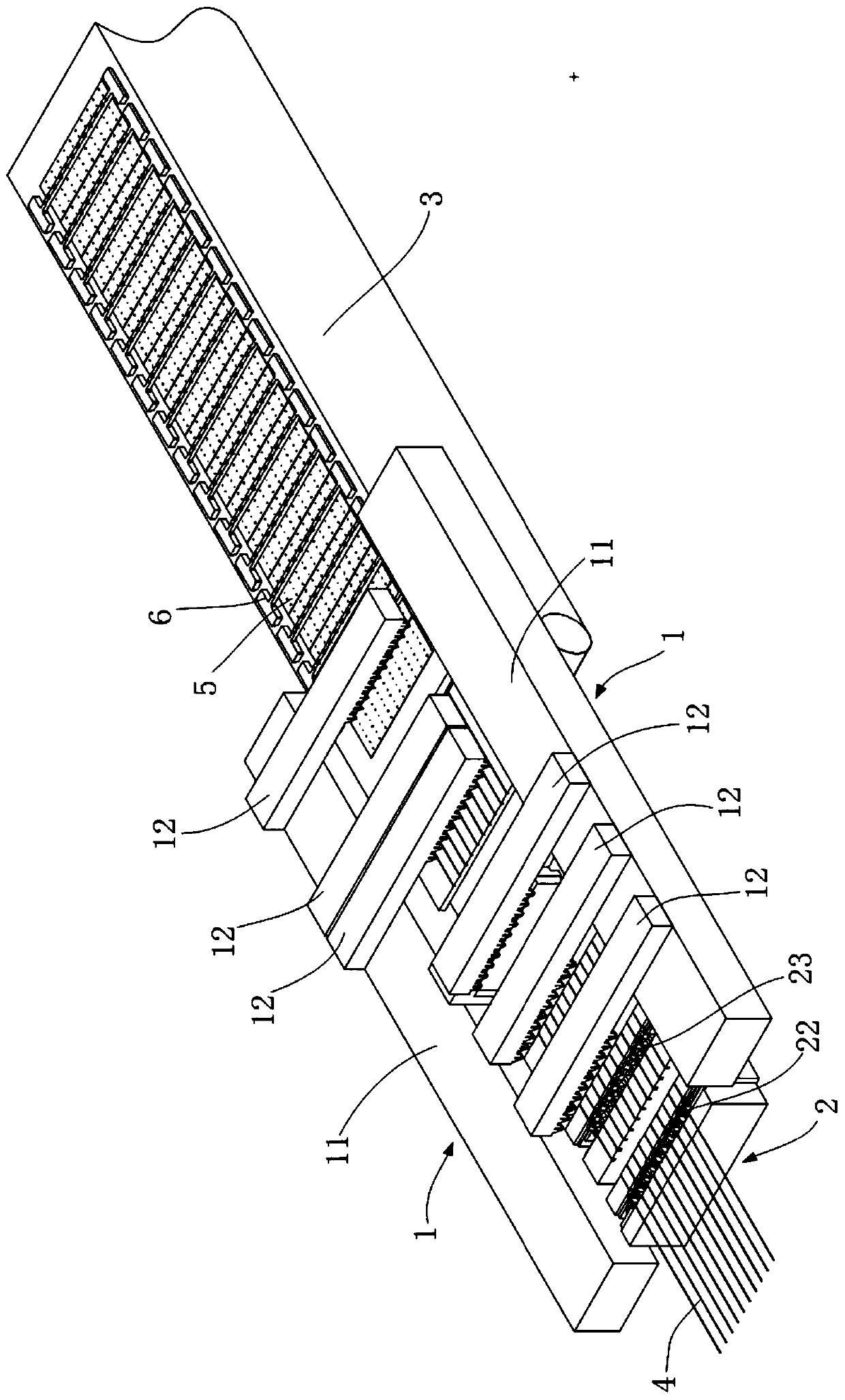
[0038] The invention provides a welding strip laying device, such as figure 1 with figure 2 The welding tape laying device 1 shown includes a movable main body 11 and at least two laying mechanisms 12 provided on the mobile main body 11, wherein each laying mechanism 12 can A set of parallel welding ribbons are clamped and released, and each laying mechanism 12 is configured to be able to translate relative to the moving body 1. Preferably, each of the laying mechanisms 12 is configured to be able to move up and down relative to the moving main body 11.
[0039] Each laying mechanism 12 may be configured to include a mounting frame capable of translation and/or lifting relative to the movable body 11 and a plurality of clamping jaws arranged side by side on the mounting frame for clamping the welding ribbon.
[0040] The specific process of using the welding tape laying device 1 to lay the welding tape is as follows: first, the welding tape laying device 1 clamps at least two sets of welding tapes (each laying mechanism 12 clamps a set of welding tapes), and then controls the moving main body 11 Move each laying mechanism 12 to the welding conveyor 3, the first laying mechanism 12 moves independently (translation, or translation and lifting) relative to the moving body 11 to lay the welding tape on the welding conveyor 3, and then the cell transport device is laid For the battery slices, the second laying mechanism 12 independently moves and lays the welding ribbon relative to the mobile main body 11, and the battery slice conveying device lays another battery slice.....Each laying mechanism 12 and the battery slice conveying device alternately lay the welding ribbon and battery The battery slices are stacked on the back half of the welding ribbon, and the first half of the latter group of welding ribbons are stacked on the previous battery slice, and stacked in sequence to form a battery string. Among them, during the laying process, tooling can be further used to compress and position the welding tape on the battery sheet.
[0041] The technical solution provided by the present invention adopts the welding tape laying device 1 with at least two laying mechanisms 12 to lay the welding tape. During the laying process, the welding tape laying device 1 can transport at least two sets of welding tapes 4 to 4 at a time through the laying mechanism 12 Welding the conveying device 3, and then each laying mechanism 12 cooperates with the cell transporting device in turn to lay the welding tape, which greatly improves the laying efficiency of the welding tape, thereby improving the production efficiency of the battery string.
[0042] According to another aspect of the present invention, there is also provided a stacking device, the stacking device includes a welding conveying device, a cell sheet transporting device, and the above-mentioned welding tape laying device 1;
[0043] Wherein, at least two laying mechanisms 12 of the welding ribbon laying device 1 sequentially cooperate with the battery sheet conveying device to stack the battery sheets and the welding ribbon on the welding conveying device 3.
[0044] In a preferred embodiment of the present invention, the stacking equipment includes at least two welding tape laying devices 1, and at least two welding tape laying devices 1 alternately move to the welding conveyor 3 to lay the welding tape .
[0045] figure 1 It is shown that the stacking device is provided with two ribbon laying devices 1, and each ribbon laying device 1 is provided with at least two laying mechanisms 12. When one of the welding tape laying devices 1 lays the welding tape on the welding conveyor 3, the other welding tape laying device 1 clamps the welding tape (as described below, moves to the welding tape cutting device 2 to clamp and cut Ribbon).
[0046] in figure 1 In the embodiment shown, the stacking equipment further includes a welding tape cutting device 2 configured to cut the welding tape 4 into at least two sections, and the welding tape laying device 1 is provided To move to the welding tape cutting device 2 and to make each laying mechanism 12 clamp a section of welding tape from the welding tape cutting device 2 respectively.
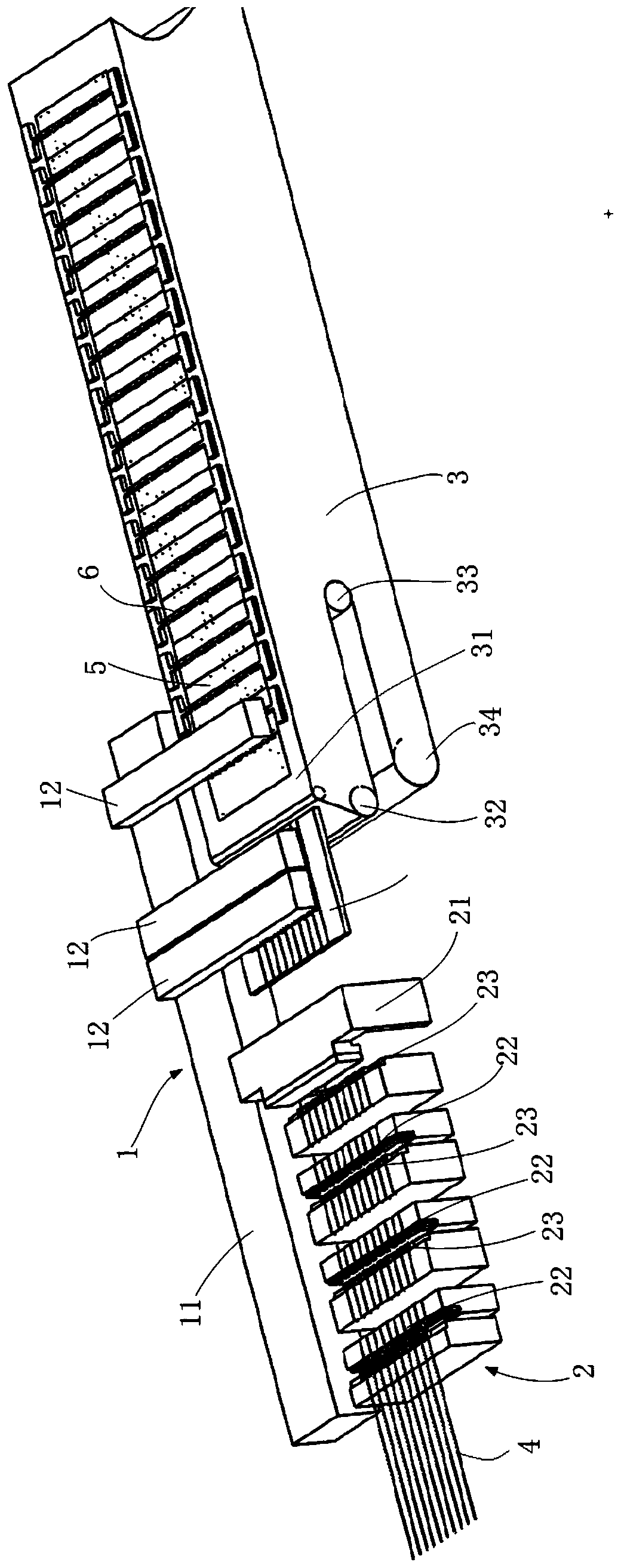
[0047] Specifically, the welding tape cutting device 2 includes:
[0048] The welding ribbon pulling mechanism 21, the welding ribbon pulling mechanism 21 is configured to pull the welding ribbon 4;
[0049] The cutting mechanism 22 is provided with at least two cutting mechanisms 22, and each of the cutting mechanisms 22 is used to cut a section of welding tape 4;
[0050] A clamping mechanism 23, each of the cutting mechanisms 22 is correspondingly provided with a clamping mechanism 23, and the clamping mechanism 23 is configured to clamp the welding ribbon 4 when the cutting mechanism 22 cuts the welding ribbon.
[0051] Wherein, the cutting mechanism 22 includes a carrying table and a cutting knife for carrying the welding ribbon. The cutting knife can be provided separately or installed on the carrying table. The clamping mechanism 23 includes a carrying table for carrying the welding ribbon. The table and the chuck. The chuck can be installed separately or on the carrying table. The carrying tables of the cutting mechanism 22 and the clamping mechanism 23 are respectively provided with guiding grooves for guiding and limiting the welding ribbon, such as figure 2 Shown. When cutting the welding ribbon 4, the welding ribbon pulling mechanism 21 pulls the welding ribbon 4 to a predetermined position so that the welding ribbon 4 is laid on each bearing platform, and then the cutting mechanism 22 and the clamping mechanism 23 are raised, or the welding ribbon pulling mechanism 21 Lower, limit the welding strip 4 in the guide groove of the bearing platform. Then the chuck of the clamping mechanism 23 clamps the welding ribbon, and the cutter of the cutting mechanism 22 rises to cut the welding ribbon from bottom to top.
[0052] The welding tape laying device 1 is moved to the welding tape cutting device 2, and each laying mechanism 12 corresponds to each section of the welding tape to be cut and clamps the corresponding welding tape.
[0053] In this embodiment, the structure of the welding conveying device 3 is as follows figure 2 As shown, a conveyor belt 31 is included. The first end of the conveyor belt 31 is configured to be able to extend step by step in a direction away from the second end and to be able to step back toward the second end. Each step away from the second end by a predetermined length, the conveyor belt 31 is turned upwards at the first end by a predetermined length, so that the upper surface of the predetermined length of the conveyor belt 31 forms an empty loading station, and the battery The sheet conveying device and the welding tape laying device 1 lay the battery sheet and the welding tape on the loading station.
[0054] Specifically, in one embodiment, such as figure 2 with image 3 As shown, the welding conveyor device 1 includes a conveyor belt 31, a base, a fixed platform 37, a stepping platform 36, and a conveyor belt driving mechanism for driving the conveyor belt 31. The fixed platform 37 is fixedly connected to the base. On the upper side, a welding station is formed above the fixed platform 37, which is used to transport the stacked cells and welding belts to the welding station for welding. The stepping platform 36 is slidably connected to the base, and the conveyor belt 31 Set on the fixed platform 37 and the stepping platform 36, the stepping platform 36 is configured to be able to move stepwise toward or away from the fixed platform 37 in the conveying direction of the conveyor belt 31;
[0055] When the stepping platform 36 moves away from the fixed platform 37 ( image 3 The conveyor belt 31 is turned from bottom to top at the end of the stepping platform 36 away from the fixed platform 37, so that the upper surface of the conveyor belt 31 moves away from the fixed platform 37 with the stepping platform 36 Into the extension.
[0056] Further, such as image 3 As shown, the conveyor belt driving mechanism for driving the conveyor belt 31 includes a driving roller 35, a first guide roller 32, a second guide roller 33, and a tension roller 34;
[0057] The driving roller 35 is arranged at the end of the fixed platform 37 away from the stepping platform 36, the first guide roller 32 is located at the end of the stepping platform 36 away from the fixed platform 37, and the first guide roller 32 and The second guide roller 33 is installed on the stepping platform 36, the tension roller 34 is located below the first guide roller 32 and the second guide roller 33, and the tension roller 34 is set to be able to move back and forth along the conveying direction of the conveyor belt 31 Adjust to tension the conveyor belt 31; the conveyor belt 31 is wound on the driving roller 35, the first guide roller 32, the second guide roller 33 and the tension roller 34 in turn, wherein the second guide roller 33 is located on the conveyor belt 31 on the transmission surface;
[0058] When the stepping platform 36 moves away from the fixed platform 37, the first guide roller 32 and the second guide roller 33 move with the stepping platform 36, and guide the conveyor belt 31 to turn upwards and extend from below. The tension roller 34 can be adjusted in the early stage to tension the conveyor belt. When the stepping platform 36 drives the first guide roller 32, the second guide roller 33 and the conveyor belt 31 to step, the tension roller 34 usually does not need to be adjusted. Of course, if the conveyor belt 31 is loose, the position of the tension roller 34 can also be adjusted for tension.
[0059] It is understandable that the way of making the conveyor belt 31 step by step to one end to form a vacant loading station is not limited to the way in which one end of the conveyor belt is turned up and extended by sliding the stepping platform, and can also be used, for example, Figure 4 The embodiment shown.
[0060] Such as Figure 4 As shown, the welding and conveying device 1 includes a conveying mechanism and a translation driving mechanism that drives the conveying mechanism to translate. The conveying mechanism includes a base, a driving roller 38, a driven roller 39, and the conveyor belt 31. The driving roller 38 and The driven roller 39 is installed on the base, the two ends of the conveyor belt 31 are respectively wound on the driving roller 38 and the driven roller 39; the translation driving mechanism (not shown in the figure) is connected On the base to drive the base to move back and forth along the conveying direction of the conveyor belt 31;
[0061] During the stepwise movement of the conveying device from the second end toward the first end under the drive of the translation drive mechanism, the conveying belt 31 stepwise conveys the same distance toward the second end, thereby The first end of the conveyor belt 31 forms the empty loading station. Such as image 3 As shown in, the translation drive mechanism drives the conveying device to move at speed v1 and in the direction indicated by the left arrow, while the conveyor belt 31 moves at speed v1 and in the direction indicated by the right arrow. In the process of the belt 31 stepping toward the first end (that is, to the left), the first end of the conveyor belt is always in an empty state, forming a loading station for receiving the battery sheet and the welding ribbon.
[0062] The welding conveyor device 3 provided by the present invention is provided with a conveyor belt 31 that can be extended step by step toward one end of the welding belt laying device 1 to form a vacant loading station. The conveyor belt 31 extends once every step, the welding belt laying device 1 and the battery sheet The conveying device is laid once, and when a preset number of welding tapes and battery sheets are laid on the conveyor belt 31, the conveyor belt 31 transports the stacked welding tapes and battery sheets to the welding station for welding.
[0063] According to figure 1 The illustrated embodiment describes the specific process of stacking the solder ribbon and the battery string using the stacking device provided by the present invention.
[0064] First, the ribbon pulling device 21 of the ribbon cutting device 2 pulls the ribbon 4 to extend to the cutting position, the clamping mechanism 23 clamps the ribbon 4, and the cutting mechanism 23 cuts the ribbon into at least two sections. .
[0065] The welding tape laying device 1 is moved to the welding tape cutting device 2, and each laying mechanism 12 is respectively moved to above a section of welding tape and clamps the section of welding tape;
[0066] The welding belt laying device 1 clamps the welding belt and moves to the welding conveying device 3. The conveyor belt 31 of the welding conveying device 3 extends step by step to one end to form an empty feeding station. The first laying mechanism 12 on the welding belt laying device 1 corresponds to Corresponding to the movement of the mobile body 11, the first set of welding tapes are laid on the loading station of the conveyor belt 31, and the cell handling device transports the first cell 5, and places the first cell 5 on the first set of welding tape. In the second half, the cell transport device can be configured to simultaneously transport the cell 5 and the tooling 6. When the cell 5 is placed in the second half of the welding tape, the tooling 6 is pressed against the welding tape. The first half of the positioning is carried out, of course, an independent tooling transport device can also be set to transport the tooling 6; then the second laying mechanism 12 lays the second set of welding tape, so that the first half of the second set of welding tape is pressed against the first cell Above 5, the cell transporting device transports the next cell 5 and tooling 6 and stacks them on the previous set of soldering tape; then the third laying mechanism 12 and the cell transporting device alternately lay the soldering tape and the cell again.
[0067] among them, figure 1 Two welding tape laying devices 1 are shown. One of the welding tape laying devices 1 when laying welding tape on the welding conveyor 3, the other welding tape laying device 1 can be moved to the welding tape cutting position to clamp the cut Welding tape. The two welding tape laying devices 1 are alternately moved to the welding conveyor 3 to lay the welding tape, which can improve the stacking efficiency of the battery sheet and the welding tape.
[0068] When the conveyor belt 31 of the welding conveying device 3 steps to one end by a preset number of steps, so that the battery slices and welding belts are laid to reach the preset number, the conveyor belt 31 conveys the preset number of welding tapes and battery slices to the welder. Position for welding.
[0069] According to another aspect of the present invention, there is also provided a stacking method, the stacking method comprising:
[0070] Controlling the welding strip laying device 1 to clamp at least two sets of welding strips to move to the welding conveying device 3, wherein each set of welding strips is clamped by a laying mechanism 12 of the welding strip laying device 1;
[0071] Control each of the laying mechanisms 12 to move independently to lay the welding tape on the welding and conveying device 3, and the first one or both of the battery sheet transporting device to lay the battery sheets and the tooling in the welding and conveying device 1, the laying mechanism 12 Cooperating with the cell handling device to stack the cells and the welding ribbon or stack the cells, tooling and the welding ribbon.
[0072] Preferably, there are two welding tape laying devices;
[0073] The control welding strip laying device 1 clamps at least two sets of welding strips to move to the welding conveying device 3, specifically: controlling the two welding strip laying devices 1 to alternately move to the welding conveying device 3 in cycles.
[0074] The stacking method further includes: pulling a set of welding ribbons to extend and cutting the extended welding ribbons into at least two sections;
[0075] Each laying mechanism 12 of the welding tape laying device 1 clamps a section of cut welding tape.
[0076] Before controlling each of the laying mechanisms 12 to move independently to lay the welding tape on the welding and conveying device 3, and before the first one or both of the battery sheet and tooling is laid by the battery sheet conveying device on the welding and conveying device, the method Also includes:
[0077] The first end of the conveyor belt 31 that controls the welding and conveying device 3 extends step by step in a direction away from the second end, wherein the conveyor belt 31 steps a predetermined length in the direction away from the second end, and the conveyor belt 31 is Turn the predetermined length upward at the first end, so that the upper surface of the predetermined length of the conveyor belt 31 forms an empty loading station;
[0078] The cell transport device and the laying mechanism 12 lay the cell and the soldering tape at the loading station, or lay the cell, the tooling and the soldering tape at the loading station.
[0079] The stacking method provided by the present invention can be implemented using the stacking equipment described above, and the specific implementation process will not be further described here.
[0080] The preferred embodiments of the present invention are described in detail above with reference to the accompanying drawings, but the present invention is not limited thereto. Within the scope of the technical concept of the present invention, a variety of simple modifications can be made to the technical solution of the present invention, including individual specific technical features combined in any suitable manner. In order to avoid unnecessary repetition, various possible combinations are not described separately in the present invention. However, these simple modifications and combinations should also be regarded as the disclosed content of the present invention, and all belong to the protection scope of the present invention.