Low-frequency broadband electromagnetic-piezoelectric-friction combined type vibration energy collector

A vibration energy harvesting, composite technology, applied in the direction of generator/motor, piezoelectric effect/electrostrictive or magnetostrictive motor, electric component, etc. Low resonance frequency and other problems, to achieve the effect of enriching power output characteristics, strong environmental adaptability, and reducing collision energy consumption

Active Publication Date: 2020-08-21
HENAN UNIVERSITY OF TECHNOLOGY
View PDF9 Cites 7 Cited by
  • Summary
  • Abstract
  • Description
  • Claims
  • Application Information

AI Technical Summary

Problems solved by technology

[0003] At present, vibration energy harvesters generally have the problems of low resonance frequency and narrow working bandwidth. It is difficult to efficiently collect low-freque

Method used


Image

  • Low-frequency broadband electromagnetic-piezoelectric-friction combined type vibration energy collector
  • Low-frequency broadband electromagnetic-piezoelectric-friction combined type vibration energy collector
  • Low-frequency broadband electromagnetic-piezoelectric-friction combined type vibration energy collector

Examples


Embodiment 1

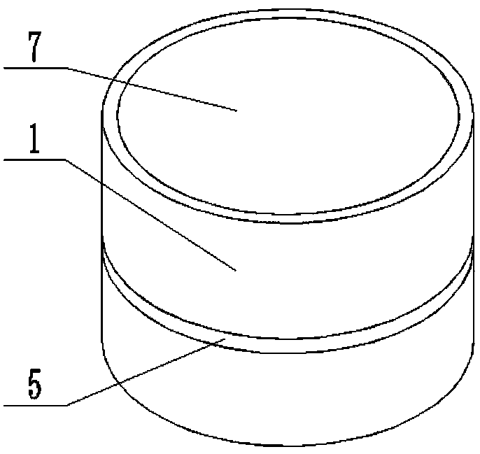
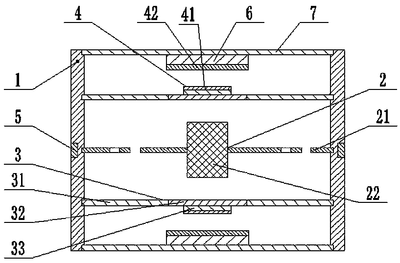
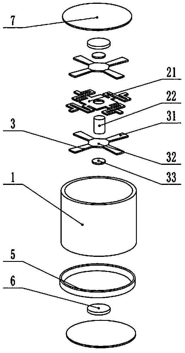
[0023] Such as Figure 1-Figure 4 As shown, a low-frequency broadband electromagnetic-piezoelectric-friction composite vibration energy harvester includes a housing 1, the upper and lower ends of the housing 1 are respectively fixed with end caps 7, and the inner surfaces of the two end caps 7 are fixed A fixed magnet 6 is installed, a moving magnet mechanism 2 is installed in the middle part of the housing 1, and an induction coil 5 is installed at the moving magnet mechanism 2 on the outer peripheral wall of the casing 1, between the moving magnet mechanism 2 and the fixed magnet 6 on the upper side An elastic limit mechanism 3 and a friction generating mechanism 4 are provided in sequence, and an elastic limit mechanism 3 and a friction generating mechanism 4 are also arranged in sequence between the moving magnet mechanism 2 and the fixed magnet 6 on the lower side. The moving magnet mechanism 2 and the elastic There is a gap between the limiting mechanisms 3, the central ...

Embodiment 2

[0035] Such as Figure 1-Figure 4 As shown, a low-frequency broadband electromagnetic-piezoelectric-friction compound vibration energy harvester includes a housing 1, the upper and lower ends of the housing 1 are respectively fixed with end caps 7, and the inner end faces of the two end caps 7 are all fixed A fixed magnet 6 is installed, a moving magnet mechanism 2 is installed in the middle part of the housing 1, and an induction coil 5 is installed at the moving magnet mechanism 2 on the outer peripheral wall of the casing 1, between the moving magnet mechanism 2 and the fixed magnet 6 on the upper side An elastic limit mechanism 3 and a friction generating mechanism 4 are provided in sequence, and an elastic limit mechanism 3 and a friction generating mechanism 4 are also arranged in sequence between the moving magnet mechanism 2 and the fixed magnet 6 on the lower side. The moving magnet mechanism 2 and the elastic There is a gap between the limiting mechanisms 3, the cent...


PUM


Abstract

The invention relates to a low-frequency broadband electromagnetic-piezoelectric-friction combined type vibration energy collector. The energy collector comprises a shell, end covers are fixed to theupper end and the lower end of the shell correspondingly. Fixed magnets are fixedly installed on the inner surfaces of the two end covers, a movable magnet mechanism is installed in the middle in theshell, an induction coil is installed at the position, where the movable magnet mechanism is located, of the peripheral wall of the shell, and an elastic limiting mechanism and a friction power generation mechanism are sequentially arranged between the movable magnet mechanism and the fixed magnets on the two sides respectively. According to the invention, the multi-stable vibration system and thetwo-degree-of-freedom vibration system are utilized to enable the vibration energy collector to respond to low-frequency vibration in a wide range; meanwhile, the piezoelectric effect and the triboelectric effect are used for collecting collision energy, collision energy consumption is reduced, and the vibration energy collector further has the advantages of low-frequency broadband response capacity and efficient energy collection at the same time.

Description

technical field [0001] The invention relates to the technical field of energy collection, in particular to a low-frequency broadband electromagnetic-piezoelectric-friction compound vibration energy collector. Background technique [0002] With the wide application of wireless sensor network technology, the chemical battery as the main power supply method has the problems of short life and limited energy storage. The means are not suitable for workplaces where secondary entry is difficult, locations are scattered, and the working environment is harsh. As a green energy harvesting technology, the vibration energy harvester can convert the vibration energy widely present in the surrounding environment into electrical energy, for example, the vibration of bridges, the vibration formed by driving vehicles, and the vibration generated by human activities. Vibration in the environment exists in every corner of nature at all times, and is not affected by weather, season and tempera...

Claims


Application Information

Patent Timeline
IPC IPC(8): H02K35/02H02K5/04H02N2/18H02N1/04
CPCH02K35/02H02K5/04H02N2/186H02N1/04
Inventor 张坤冯伟刘保国康克家常永程敏
Owner HENAN UNIVERSITY OF TECHNOLOGY
Why Eureka
Try Eureka