Check patentability & draft patents in minutes with Patsnap Eureka AI!

Electromagnetic contactor

A technology of electromagnetic contactors and moving contacts, which is applied in the direction of electromagnetic relays, relays, detailed information of electromagnetic relays, etc., and can solve a large number of processing steps and other problems

Inactive Publication Date: 2003-07-23
FUJI ELECTRIC FA COMPONENTS & SYST CO LTD
View PDF4 Cites 0 Cited by
  • Summary
  • Abstract
  • Description
  • Claims
  • Application Information

AI Technical Summary

Problems solved by technology

[0009] In addition, in Figure 12 In this case, since the top surface 5A of the main core 5 and the top surface 4A of the yoke 4 constitute the magnetic pole surface, in order to make the two coplanar, they must be ground, which in turn requires a large number of processing steps
[0010] Also, the main core 5 is joined to the yoke 4 by resistance welding, however such welding requires a large number of processing steps

Method used


Image

  • Electromagnetic contactor
  • Electromagnetic contactor
  • Electromagnetic contactor

Examples


Embodiment Construction

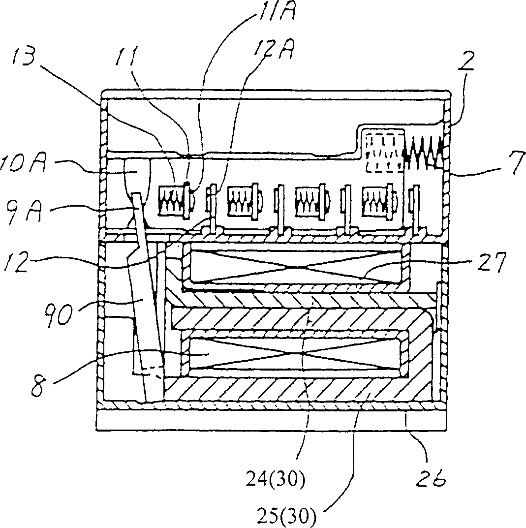
[0032] Hereinafter, it will be described through the embodiments of the present invention. figure 1 A cross-sectional view of a structure of an electromagnetic contactor according to an embodiment of the present invention is shown. The difference between this electromagnetic contactor and the similar traditional technology is that the iron core 30 includes a first iron core 25 shaped like a letter "U" and a second iron core 24 bent like a letter "L", and the first iron core and the second iron core The left sides of the iron cores 24 and 25 face the iron sheet 90, and the first iron core 25 is placed on the bottom of the lower casing 26. Other parts of the structure are the same as those of conventional devices. Therefore, the same components are denoted by the same reference numerals, and their detailed descriptions are omitted here.

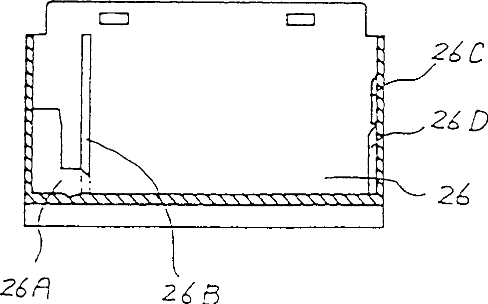
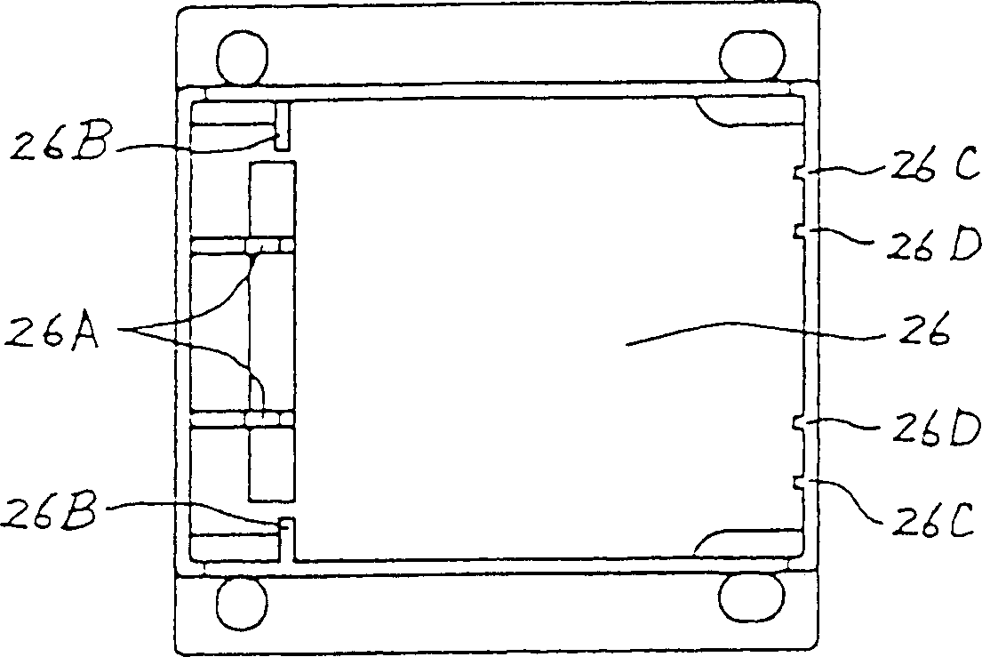
[0033] figure 2 , 3 and 4 are figure 1 Sectional view, plan view and perspective view of the middle and lower casing 26. In each figu...


PUM


Abstract

An electromagnetic contactor includes an iron core (30) formed of a first core (25) bent in a U-shape, and a second L-shaped core (24). A coil (8) is wound around a spool disposed on an upper arm of the first core (25) and the second core (24) to form a main leg while a lower arm of the first core constitutes a yoke. Thus, the iron core members can be processed by a press machine operating at a normal cutting speed, and welding and polishing operations can be eliminated to thereby reduce the number of processing steps required.

Description

Technical field: [0001] The invention relates to an electromagnetic contactor with a movable hinge-shaped iron sheet, in particular to an electromagnet iron core structure with low production cost. Background technique: [0002] Figure 11 It is a cross-sectional view of a traditional electromagnetic contactor structure. The core 3 consisting of the main core 5 and the yoke 4 and the coil 8 wound on the main core 5 are placed in the lower case 1, and the yoke 4 is mounted on the bottom 1A of the lower case 1. A bracket 10 movable laterally is placed in the upper casing 2 and can move leftward when receiving the force of the return spring 7 between the bracket 10 and the side wall of the upper casing 2 . The moving contact 11 is mounted on the movable bracket 10 via a contact spring 13 . The fixed contact 12 is fixed in the upper casing, and the contact 12A connected to the fixed contact 12 is opposite to the contact 11A connected to the moving contact 11, so that the conta...

Claims


Application Information

Patent Timeline
Patent Type & Authority Patents(China)
IPC IPC(8): H01H50/36H01H51/06
CPCH01H50/36H01H50/44
Inventor 柴田胜美町田谨斎平松悦也広田耕人川崎诚
Owner FUJI ELECTRIC FA COMPONENTS & SYST CO LTD
Features
  • R&D
  • Intellectual Property
  • Life Sciences
  • Materials
  • Tech Scout
  • Unparalleled Data Quality
  • Higher Quality Content
  • 60% Fewer Hallucinations
Learn More