A mold structure for installing copper nuts on insulating seats

A technology of copper nut and insulating seat, applied in the direction of coating, can solve the problems of extending the effective thread length of copper nut, insufficient effective thread of copper nut, and high success rate of injection molding of insulating seat, and achieves good injection molding effect and structure. Simple, high injection molding success rate

Active Publication Date: 2021-01-05
NINGBO JOYSONQUIN AUTOMOTIVE SYST HLDG CO LTD
View PDF7 Cites 0 Cited by
  • Summary
  • Abstract
  • Description
  • Claims
  • Application Information

AI Technical Summary

Problems solved by technology

[0004] Aiming at the deficiencies and defects of the existing technology, a mold structure for installing copper nuts on the insulating seat is provided. The structure is simple, the injection molding effect is good, and the success rate of injection molding of the insulating seat is high, and the effective thread length of the copper nut is extended at the same time. , to solve the problem of not enough effective threads of the copper nut without extending the length of the copper nut

Method used


Image

  • A mold structure for installing copper nuts on insulating seats
  • A mold structure for installing copper nuts on insulating seats
  • A mold structure for installing copper nuts on insulating seats

Examples


Embodiment Construction

[0021] The present invention is further explained in conjunction with the accompanying drawings.

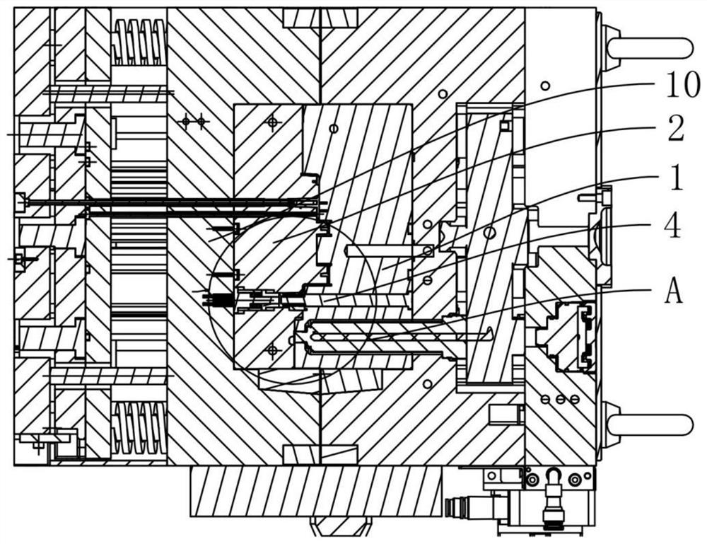
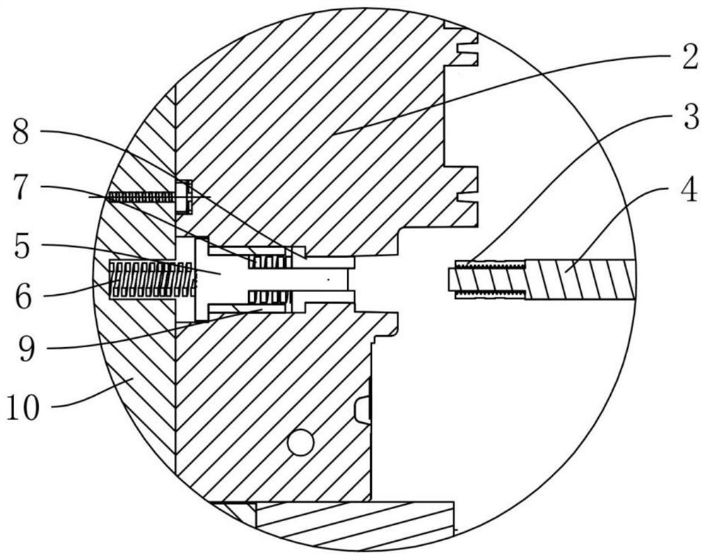
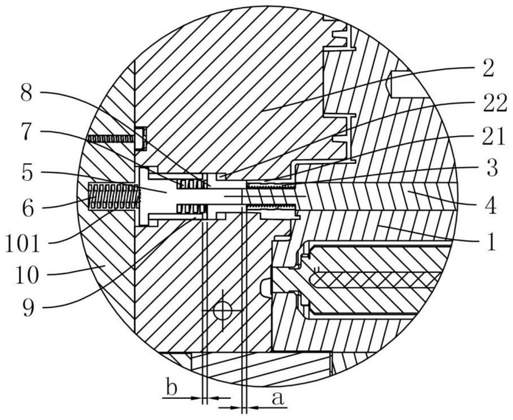
[0022] see Figure 1 to Figure 5 A mold structure for installing a copper nut 3 on an insulating seat is shown, which includes a front mold core 1 and a rear mold core 2 which are arranged oppositely front and back, and a copper nut 3 is installed on the front mold core 1 through a mounting column 4, The copper nut 3 is sleeved on the mounting column 4 and the end of the mounting column 4 protrudes from the copper nut 3, and the mounting column 4 is provided with a stop step that cooperates with the copper nut 3, so that the copper nut 3 can only be to move.

[0023] The rear mold core 2 is provided with a molding hole 21 matched with the copper nut 3 and an installation cavity 22 connected with the molding hole 21. During injection molding, the injection molding medium enters the molding hole 21 to form a product. The mounting cavity 22 is movably provided with a spring post 5...


PUM


Abstract

The invention discloses a die structure for mounting a copper nut on an insulating base. The die structure comprises a front die core and a back die core. A mounting column is arranged on the front die core, the copper nut is arranged on the mounting column in a sleeving manner, a forming hole and a mounting cavity are formed in the back die core, an elastic column and an elastic cover are movablyarranged in the mounting cavity, one end of the elastic cover stretches into the forming hole and a through hole where the elastic column stretches into is formed in the elastic cover, and a cushioncover is further arranged between the elastic column and the elastic cover. When the front die core and the back die core are assembled, the mounting column and the copper nut stretch into the forminghole, a forming space where an injection medium flows into is formed between the copper nut and the inner wall of the forming hole, an eject force of the elastic cover is greater than frictional force generated by the injection medium to the copper nut in the forming space during injection molding, and the eject force of the elastic cover and the eject force of the elastic column are smaller thanpressure generated by the injection medium in the forming hole to the elastic cover during injection molding. The die structure is simple in structure and good in injection molding effect, the injection molding success rate of the insulating base is high, and meanwhile, the effective thread length of the copper nut is prolonged.

Description

technical field [0001] The invention relates to the technical field of molds, in particular to a mold structure for installing copper nuts on insulating seats. Background technique [0002] In the current stage of electric vehicles, the connection between the conductor and the conductor needs to be fixed and supported, and the conductor needs to be insulated from other conductors or semiconductors. A simple and effective way to meet this requirement is to use insulation seat to realize the safe and reliable work of the conductor. [0003] At present, the structure of the insulating seat is a seat body and a copper nut arranged on the seat body, wherein the copper nut is placed in the seat body with one side exposed, and the conductor is fixed and supported by the copper nut. Insulation, when the insulating seat is manufactured, the through hole is first injection molded on the seat body, and at the same time, the injection molded parts of the cover are added for assembly to...

Claims


Application Information

Patent Timeline
Patent Type & Authority Patents(China)
IPC IPC(8): B29C45/26B29C45/14
CPCB29C45/14065B29C45/14639B29C45/26
Inventor 王龙胜郑海笑郭剑康
Owner NINGBO JOYSONQUIN AUTOMOTIVE SYST HLDG CO LTD
Why Eureka
Try Eureka