
Hydraulic raised floor

A raised floor and floor technology, applied in the direction of motor vehicles, superstructures, and vehicles for freight, can solve the problems of residual goods, not easy to clean, easy to damage hydraulic raised floors, etc., achieves simple design, is conducive to long-term Promote and improve work efficiency

Active Publication Date: 2020-08-25
美欣达欣智造(湖州)科技有限公司
View PDF3 Cites 0 Cited by
  • Summary
  • Abstract
  • Description
  • Claims
  • Application Information

AI Technical Summary

Problems solved by technology

[0002] In the process of truck transportation, more and more access floors are used for loading and unloading. However, due to the gaps between the slats of the access floor, the use of the access floor has certain limitations, making large Part of the access floor can only transport some larger goods such as glass. The Chinese Patent Publication (Notice) No. is CN2818223, and the patent name is the hydraulic access floor loading and unloading mechanism. Movement, the cargo is under the action of gravity and friction to realize the horizontal loading and unloading of glass and other goods, but due to the limitation of the shape of the slats, there are gaps between the slats, and there are gaps between the slats. Relative movement, even if the gap is very small, it is difficult for dust to enter, but in the process of relative movement, small particles of goods will still enter the gap, so its scope of use is very limited, only suitable for large goods, for grain, sand and gravel It is not suitable for loose and small-particle goods such as coffee beans. Small-particle goods will enter the gap with the relative movement between the slats, affecting the movement of the slats. There will be tiny particles such as dust entering the gap, not only it is not easy to clean and clean, but the hydraulic raised floor is easy to be damaged, and the maintenance rate is high
[0003] At the same time, when the raised floor unloads bulk goods, since the three hydraulic rods on the raised floor are pushed forward at one time, and then return to their original positions one by one, they will always be transported to the final hydraulic raised floor. There are cargoes remaining, which cannot be unloaded completely, so it is necessary to propose a hydraulic raised floor that can not only solve the cargo residues but also facilitate the loading and unloading of bulk cargoes to overcome these problems

Method used


Image

  • Hydraulic raised floor
  • Hydraulic raised floor
  • Hydraulic raised floor

Examples


Embodiment Construction

[0025] The technical solutions in the embodiments of the present invention will be clearly and completely described below in conjunction with the accompanying drawings in the embodiments of the present invention. Obviously, the described embodiments are only a part of the embodiments of the present invention, rather than all the embodiments. Based on the embodiments of the present invention, all other embodiments obtained by those of ordinary skill in the art without creative work shall fall within the protection scope of the present invention.

[0026] In the description of the present invention, it should be understood that the terms "center", "longitudinal", "transverse", "length", "width", "thickness", "upper", "lower", "front", " Back", "Left", "Right", "Vertical", "Horizontal", "Top", "Bottom", "Inner", "Outer", "Clockwise", "Counterclockwise", "Axial", The orientation or positional relationship indicated by "radial", "circumferential", etc. is based on the orientation or p...


PUM


Abstract

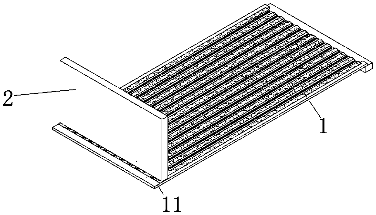
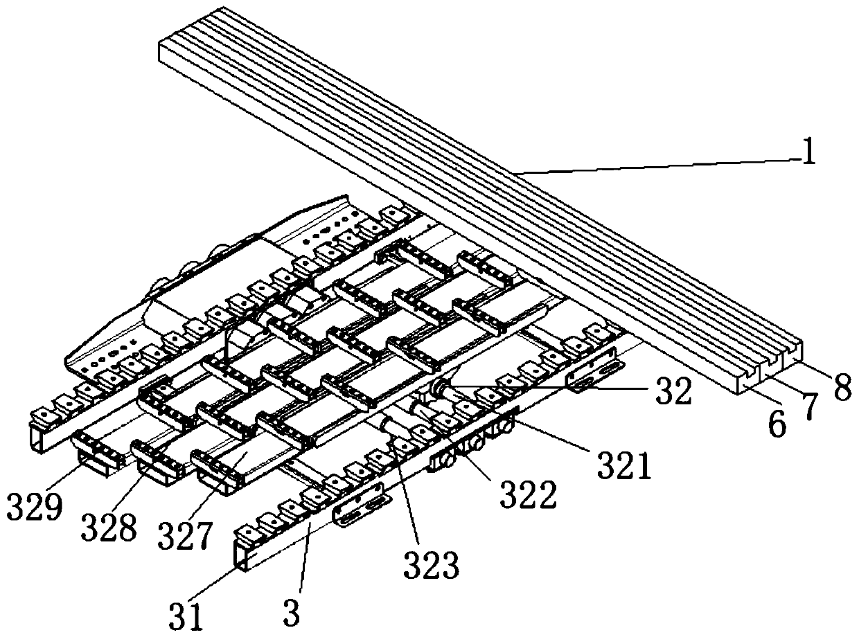
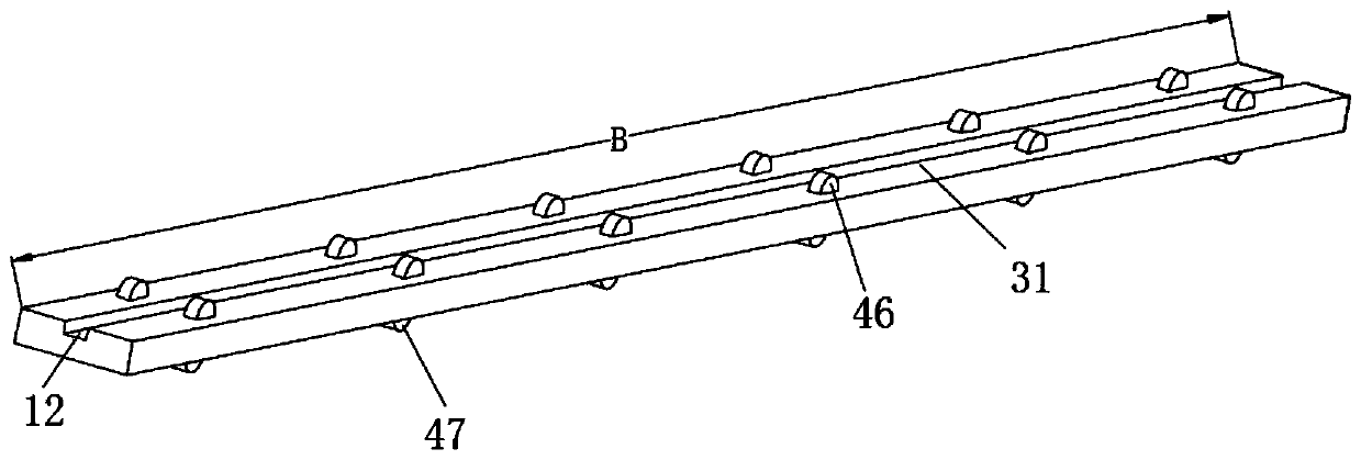
The invention relates to a hydraulic raised floor, which comprises a floor strip group. A baffle is arranged on the face, where goods are placed, of the floor strip group. The bottom of the baffle istightly attached to the upper surface of the floor strip group. The other surface of the floor strip group is fixedly connected with a hydraulic push rod mechanism; when bulk cargoes need to be unloaded, the baffle is located at the unloading starting end, the hydraulic push rod synchronously pushes the raised floor forwards; then the hydraulic push rods sequentially return one by one; the hydraulic push rod is blocked by the baffle, goods left on the floor strip can be blocked by the baffle, in each return process of the hydraulic push rod, the goods left on the floor strip can be blocked, complete unloading is achieved, later manual cleaning is not needed, through the simple and ingenious design, the working efficiency is improved, and long-term popularization of products is facilitated.

Description

Technical field [0001] The invention relates to the field of loading and unloading mechanisms, in particular to a hydraulic raised floor. Background technique [0002] In the process of truck transportation, more and more raised floors are used for loading and unloading. However, due to the gaps between the raised floor slats and the slats, the use of raised floors has certain limitations, making the large Part of the raised floor can only transport some bulky goods such as glass. The Chinese Patent Publication (Announcement) No. is CN2818223, and the patent document entitled Hydraulic Raised Floor Loading and Unloading Mechanism discloses that several sets of floor strips are driven by hydraulic cylinders. Movement, the goods are under the action of gravity and friction to realize the horizontal loading and unloading of goods such as glass, but due to the limitation of the slat shape, there is a gap between the slats and the slats. Relative movement, even if the gap is very sma...

Claims


Application Information

Patent Timeline
Patent Type & Authority Applications(China)
IPC IPC(8): B60P1/00B60P1/56B62D33/00
CPCB60P1/00B60P1/56B62D33/00
Inventor 丁永峰张健邓凌云
Owner 美欣达欣智造(湖州)科技有限公司
Learn More