
Engine test bench, engine thrust test system and test method

A technology of engine and test bench, which is applied in the direction of engine testing, jet engine testing, gas turbine engine testing, etc. It can solve problems such as the influence of engine accuracy, reduce the risk of device damage, facilitate calibration, and ensure device stability. Effect

Active Publication Date: 2022-03-11
INST OF ENGINEERING THERMOPHYSICS - CHINESE ACAD OF SCI +1
View PDF4 Cites 0 Cited by
  • Summary
  • Abstract
  • Description
  • Claims
  • Application Information

AI Technical Summary

Problems solved by technology

[0002] The engine test bench is a test device used to fix the engine and measure the thrust of the engine. The existing aero-engine test bench is usually connected to the support surface in the form of roof suspension or ground support, and uses spring sheets or sliding guide rails to bear the weight of the engine. and limit the direction of movement of the engine
[0003] In order to ensure the accuracy of the thrust test results, it is necessary to minimize the interference of the test device on the test results. However, the spring leaf and conventional sliding guide rails used in the existing device will still produce certain resistance to the movement of the engine to be tested, especially for small aeroengines However, this resistance still has a great influence on the accuracy of the engine performance test

Method used


Image

  • Engine test bench, engine thrust test system and test method
  • Engine test bench, engine thrust test system and test method
  • Engine test bench, engine thrust test system and test method

Examples


Embodiment Construction

[0036] In the following, the present invention will be specifically described through exemplary embodiments. It should be understood, however, that elements, structures and characteristics of one embodiment may be beneficially incorporated in other embodiments without further recitation.

[0037] It should be noted that, in the description of the present invention, the terms "inner", "outer", "upper", "lower", "left", "right", "front", "rear" and the like indicate directions or positions The relationship is based on the positional relationship shown in the drawings, and is only for the convenience of describing the present invention and simplifying the description, but does not indicate or imply that the referred device or element must have a specific orientation, be constructed and operated in a specific orientation, and therefore cannot be understood To limit the present invention.

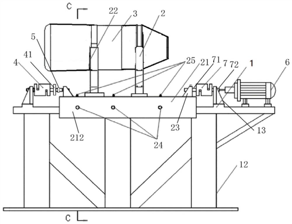
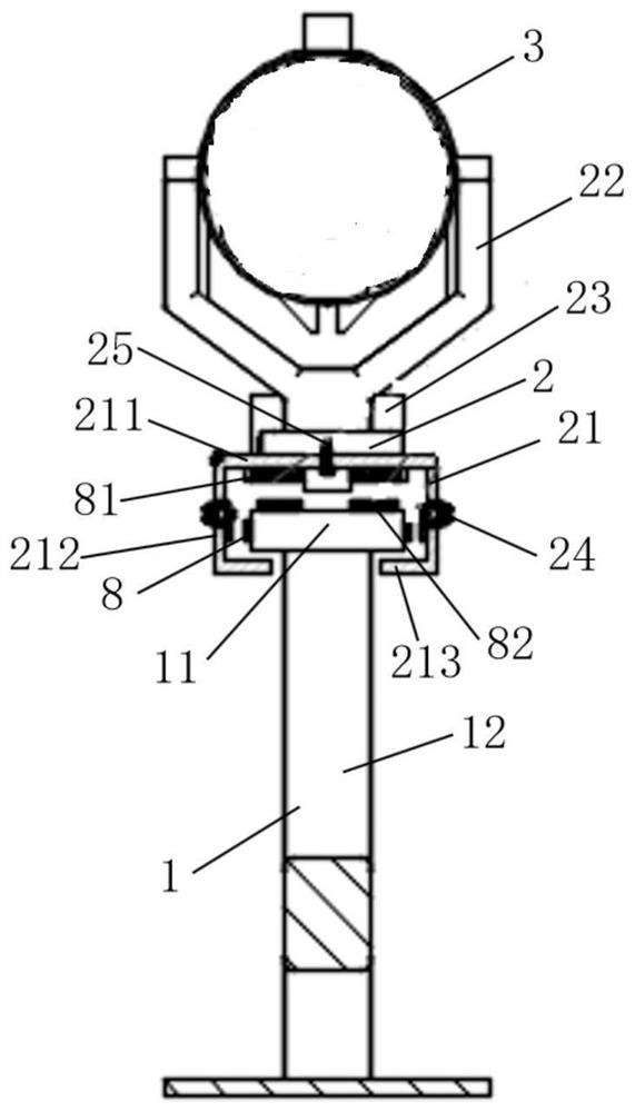
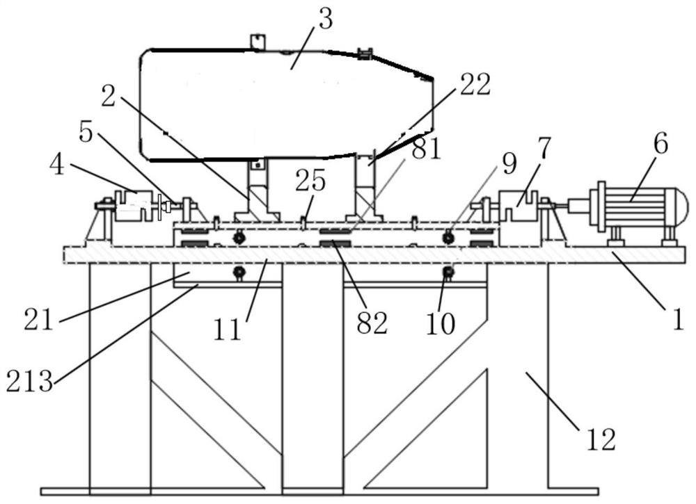
[0038] like Figures 1 to 6 Shown, a kind of engine test stand, comprises the fixed frame ...


PUM


Abstract

The invention discloses an engine test bench, an engine thrust test system and a test method. The engine test bench includes a fixed frame fixed on a support plane for fixedly installing the movable frame of the engine to be tested, and is characterized in that the fixed frame is provided with straight slide rails, and a door-shaped sliding rail is fixedly arranged under the movable frame. block, the door-shaped slider is erected on the straight slide rail, and is slidably matched with the straight slide rail, the straight slide rail and the door-shaped slider are set as a magnetic levitation slide rail and a magnetic levitation slider, and the straight slide rail A damping unit is arranged between the gate-shaped slider and the damping unit is installed in the gate-shaped groove of the gate-shaped slider. The damping unit includes a plurality of damping wheels that can roll along the direction in which the straight slide rail is set. , the shock absorbing unit is not in contact with the straight slide rail when the door-shaped slider is in a suspended state. The engine test bench can avoid the movement resistance of the test device to ensure the test results of the engine to be tested, and can also ensure the stability of the device and reduce the risk of damage to the device.

Description

technical field [0001] The invention belongs to the technical field of aero-engine testing, and in particular relates to an engine test bench, an engine thrust testing system and a testing method. Background technique [0002] The engine test bench is a test device used to fix the engine and measure the thrust of the engine. The existing aero-engine test bench is usually connected to the support surface in the form of roof suspension or ground support, and uses spring sheets or sliding guide rails to bear the weight of the engine. And limit the direction of movement of the engine. [0003] In order to ensure the accuracy of the thrust test results, it is necessary to minimize the interference of the test device on the test results. However, the spring leaf and conventional sliding guide rails used in the existing device will still produce certain resistance to the movement of the engine to be tested, especially for small aeroengines However, this resistance still has a grea...

Claims


Application Information

Patent Timeline
Patent Type & Authority Patents(China)
IPC IPC(8): G01M15/14G01M15/02G01L5/00
CPCG01M15/14G01M15/02G01L5/0038
Inventor 王月阮昌龙郭玉超于磊辉李富才李庆海孙为全李德彬王勋
Owner INST OF ENGINEERING THERMOPHYSICS - CHINESE ACAD OF SCI
Learn More