
Charging pile testing device

A technology for testing charging piles and electrical components, which is applied to measuring devices, braking of measuring devices, components of electrical measuring instruments, etc. Effect

Inactive Publication Date: 2020-08-25
宋斌强
View PDF1 Cites 5 Cited by
  • Summary
  • Abstract
  • Description
  • Claims
  • Application Information

AI Technical Summary

Problems solved by technology

[0002] Electric vehicles are powered by on-board power supplies. Because they use electric energy as the driving energy, they have little impact on the environment and have broad application prospects. The charging pile is an energy supply device for electric vehicles. The input end of the charging pile is connected to the AC power grid, and the output end is charged The plug is used to charge the on-board power supply in the electric vehicle. The charging pile can be fixed on the ground or wall, and installed in the parking lot or charging station of public buildings and residential areas. The charging performance of the charging pile will directly affect the service life of the battery pack. Therefore, corresponding The test device is used to test the charging performance of the charging pile. The core module of the existing charging pile test device is the electrical component inside the tester. Whether the electrical component can be used normally is the key to whether the test can be carried out normally, but the existing charging pile The protection of the electrical components of the pile test device is relatively weak. At the same time, the wires between the electrical components and the probe are too long and lack a wire harness structure. After each use, the wires are inconvenient to arrange, and the wires are messy before use, which makes it inconvenient to use. The patent document of Chinese invention CN201910932718.7 involves a charging pile testing device. The device lacks protection for electrical components and is relatively weak. When the tester is bumped or dropped, it is easy to cause damage to electrical components. For this reason, a charging pile test device is proposed

Method used


Image

  • Charging pile testing device
  • Charging pile testing device
  • Charging pile testing device

Examples


Embodiment

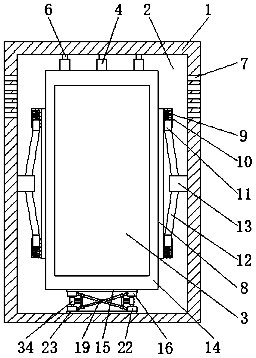
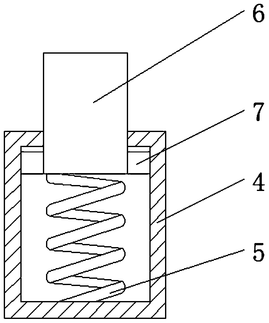
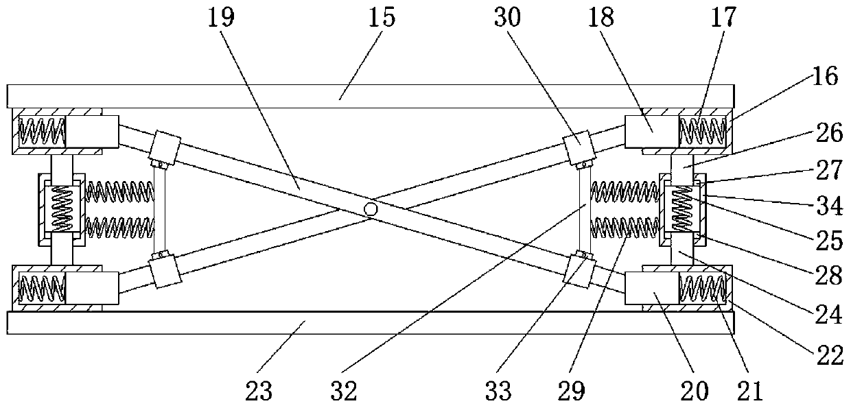
[0022] see Figure 1-6 , the present invention provides a technical solution: a charging pile testing device, including a housing 1, a damping block 2 is fixedly connected to the inner wall of the housing 1, an electrical component 3 is fixedly connected to the front surface of the damping block 2, and the upper surface of the electrical component 3 The surface is evenly and fixedly connected with the first shell 4, the bottom of the inner side wall of the first shell 4 is fixedly connected with the first spring 5, and the end of the first spring 5 far away from the first shell 4 is fixedly connected with the first support rod 6, and the second The outer wall of a support rod 6 is slidably connected to the inner wall of the first housing 4, the end of the first support rod 6 away from the first spring 5 is fixedly connected to the inner wall of the housing 1, and the lower surface of the electrical component 3 is fixedly connected with a second Two plates 15, the side of the s...


PUM


Abstract

The invention discloses a charging pile testing device. The testing device comprises a shell; a damping block is fixedly connected to the inner side wall of the shell. The front surface of the dampingblock is fixedly connected with an electric appliance element; first shells are evenly and fixedly connected to the upper surface of the electric appliance element, first springs are fixedly connected to the bottoms of the inner side walls of the first shells, first supporting rods are fixedly connected to the ends, away from the first shells, of the first springs, and the outer side walls of thefirst supporting rods are slidably connected to the inner side walls of the first shells. The damping block, the first springs, the second spring and other structures are arranged in a matched mode;a shock absorption effect is achieved between the electric appliance element and the shell; therefore, when the device falls off, buffering and force unloading effects are achieved between the electric appliance element and the shell, the electric appliance element is prevented from being damaged, the fourth plate body, the second rod body and other structures are arranged in a matched mode, a wire bunching effect can be achieved on a wire, and therefore the device is convenient to use.

Description

technical field [0001] The invention relates to the technical field of testing devices, in particular to a charging pile testing device. Background technique [0002] Electric vehicles are powered by on-board power supplies. Because they use electric energy as the driving energy, they have little impact on the environment and have broad application prospects. The charging pile is an energy supply device for electric vehicles. The input end of the charging pile is connected to the AC power grid, and the output end is charged The plug is used to charge the on-board power supply in the electric vehicle. The charging pile can be fixed on the ground or wall, and installed in the parking lot or charging station of public buildings and residential areas. The charging performance of the charging pile will directly affect the service life of the battery pack. Therefore, corresponding The test device is used to test the charging performance of the charging pile. The core module of the...

Claims


Application Information

Patent Timeline
IPC IPC(8): G01R31/00G01R1/02G01R1/14H02G3/02F16F15/067F16F15/023
CPCF16F15/023F16F15/067G01R1/02G01R1/14G01R31/00H02G3/02
Inventor 宋斌强
Owner 宋斌强
Learn More