
An adjustable permanent magnet mechanism

A permanent magnet mechanism and adjustable technology, which is applied in the direction of protection switch operation/release mechanism, adjustment of protection switch conditions, protection switch parts, etc., and can solve problems such as failure of permanent magnet mechanism action, broken magnet, insufficient contact pressure, etc.

Active Publication Date: 2022-07-08
杭州德睿达电气有限公司
View PDF3 Cites 0 Cited by
  • Summary
  • Abstract
  • Description
  • Claims
  • Application Information

AI Technical Summary

Problems solved by technology

[0002] Most DC fast circuit breakers use permanent magnet mechanism to realize the opening and closing operation, but the permanent magnet mechanism of the existing circuit breaker cannot realize the convenient and fast adjustment of the magnetic holding force. In addition, if the magnetic holding force is too large, it may be because the air gap between the moving iron core and the magnet is too small or there is no air gap. In this way, when the permanent magnet mechanism pulls in, the magnet will be broken under the impact of the moving iron core, resulting in permanent The action of the magnetic mechanism fails; if the magnetic holding force is too small, it may appear that the DC fast circuit breaker cannot be closed, the closing speed is not fast enough, or the contact pressure is not enough.
The size of the magnetic holding force is inconvenient to adjust, resulting in repeated adjustment and assembly, seriously affecting work efficiency

Method used


Image

  • An adjustable permanent magnet mechanism
  • An adjustable permanent magnet mechanism

Examples


Embodiment Construction

[0014] The technical solutions in the embodiments of the present invention will be clearly and completely described below with reference to the accompanying drawings in the embodiments of the present invention. Obviously, the described embodiments are only a part of the embodiments of the present invention, rather than all the embodiments. Based on the embodiments of the present invention, all other embodiments obtained by those of ordinary skill in the art without creative efforts shall fall within the protection scope of the present invention.

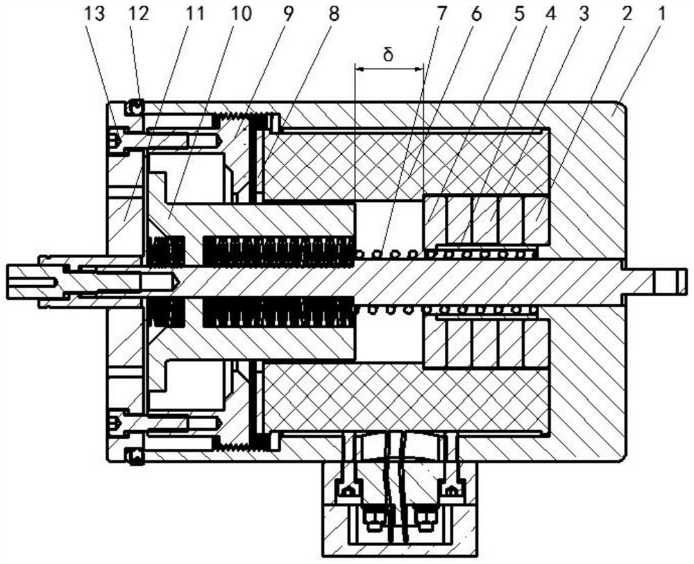
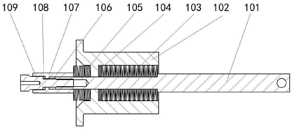
[0015] see Figure 1-2 , the present invention provides a technical solution: an adjustable permanent magnet mechanism, comprising a cylindrical hollow permanent magnet housing 1 and a moving iron core 10 arranged in the inner cavity of the permanent magnet housing 1, the permanent magnet housing 1 The inner cavity of the body 1 is also provided with a first bushing 4 which is sleeved outside the moving iron core 10, and an opening s...


PUM


Abstract

The invention discloses an adjustable permanent magnet mechanism, comprising a cylindrical hollow permanent magnet casing and a moving iron core arranged in the inner cavity of the permanent magnet casing, and a sleeve is also arranged in the inner cavity of the permanent magnet casing A first bushing outside the moving iron core is provided with an opening spring between the first bushing and the moving iron core, and a first washer, a magnet, a second washer, a coil and multiple The third washer for sheet adjustment is provided with a flange plate to compress the above components in the permanent magnet housing. The port of the permanent magnet housing is provided with an end cover, and the outer end face of the flange is provided with threaded holes. Suppose the fastening screws are fastened to the flange, the side wall of the permanent magnet housing is symmetrically provided with threaded holes near the port, and the end cover is fixed to the port of the permanent magnet housing through the conical set screws in the threaded holes superior. The permanent magnet mechanism can flexibly and quickly adjust the magnetic holding force of the permanent magnet mechanism through the screwing depth of the flange.

Description

technical field [0001] The invention relates to the field of circuit breaker components, in particular to a permanent magnet mechanism used for opening and closing operations of a DC fast circuit breaker. Background technique [0002] DC fast circuit breakers mostly use permanent magnet mechanism to realize the opening and closing operation, and the permanent magnet mechanism of the existing circuit breaker cannot realize the convenient and rapid adjustment of the magnetic holding force, and the magnetic holding force is too large. The gate speed, and the excessive magnetic holding force may be due to the fact that the air gap between the moving iron core and the magnet is too small or there is no air gap. In this way, when the permanent magnet mechanism is pulled in, the magnet will be broken under the impact of the moving iron core, resulting in permanent damage. The action of the magnetic mechanism fails; if the magnetic holding force is too small, it may occur that the D...

Claims


Application Information

Patent Timeline
Patent Type & Authority Patents(China)
IPC IPC(8): H01H71/32H01H71/74
CPCH01H71/32H01H71/7463
Inventor 江阳黄依婷涂勇
Owner 杭州德睿达电气有限公司
Learn More