
A kind of energy control method and energy storage system

An energy control and energy storage system technology, applied in the field of power electronics, can solve the problems affecting the effective utilization of battery performance, unable to meet the expansion needs of energy storage systems, and unable to achieve compatible management of new and old batteries, to ensure maximum output capacity, improve Reliability, achieve the effect of compatible management

Active Publication Date: 2022-05-24
SUNGROW POWER SUPPLY CO LTD
View PDF3 Cites 0 Cited by
  • Summary
  • Abstract
  • Description
  • Claims
  • Application Information

AI Technical Summary

Problems solved by technology

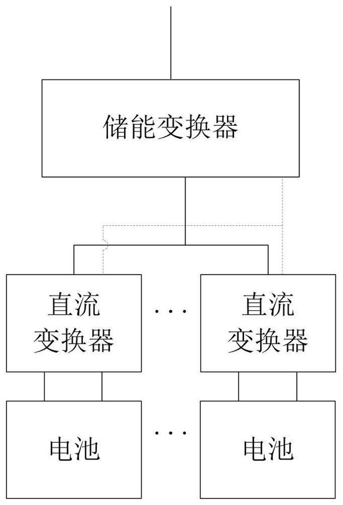
[0003] In the prior art, in order to meet the expansion requirements of the energy storage system, the simplest expansion method is to directly connect the same type of device in parallel on the DC side of the energy storage converter; however, there are corresponding problems after the expansion of the above two energy storage systems. It cannot meet the expansion requirements of the energy storage system in practical applications, therefore, a situation such as figure 2 In the energy storage system shown, the new battery is first connected in series with its own DC converter, and then connected in parallel to the DC side of the energy storage converter
[0004] However, the existing DCDC converter parallel system usually adopts master-slave control or droop control, for figure 2 The structure of the energy storage system shown is still unable to achieve compatible management of old and new batteries, which will affect the effective use of battery performance

Method used


Image

  • A kind of energy control method and energy storage system
  • A kind of energy control method and energy storage system
  • A kind of energy control method and energy storage system

Examples


Embodiment Construction

[0047] The technical solutions in the embodiments of the present application will be clearly and completely described below with reference to the drawings in the embodiments of the present application. Obviously, the described embodiments are only a part of the embodiments of the present application, but not all of the embodiments. Based on the embodiments in the present application, all other embodiments obtained by those of ordinary skill in the art without creative work fall within the protection scope of the present application.

[0048]In this application, relational terms such as first and second, etc. are only used to distinguish one entity or operation from another entity or operation, and do not necessarily require or imply that any such relationship exists between these entities or operations. an actual relationship or sequence. Also the terms "comprising", "comprising" or any other variation thereof are intended to encompass a non-exclusive inclusion such that a pro...


PUM


Abstract

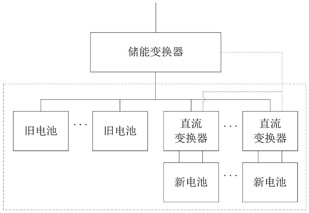
The present application provides an energy control method and an energy storage system. The energy storage converter in the energy storage system is connected to N first energy storage devices, and is connected to M second energy storage devices one by one through M DC converters. equipment. In the energy control method, firstly, the preset converter among the M DC converters in the energy storage system balances the SOC between the first energy storage device and the second energy storage device; and the energy storage The general controller in the system controls the average power of each energy storage device; then, each DC converter controls its own operating power according to the above-mentioned balanced adjustment results and power average control results, thereby realizing SOC balanced adjustment and power The decoupling of the average control realizes the compatible management of the first energy storage device and the second energy storage device, improves the reliability of the control in the energy storage system; and also ensures the fast response and maximum output capacity of the energy storage system .

Description

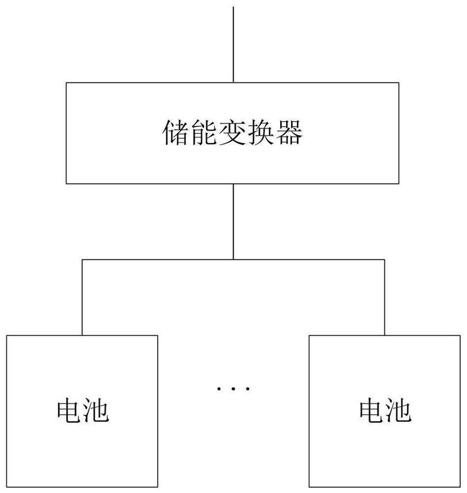
technical field [0001] The invention relates to the technical field of power electronics, in particular to an energy control method and an energy storage system. Background technique [0002] Usually, the internal structure of the energy storage system exists in two forms, one such as Figure 1a As shown, multiple batteries are directly connected in parallel to the DC side of the energy storage converter; another such as Figure 1b As shown, multiple batteries are first connected in series with their respective DC converters, and then connected in parallel to the DC side of the energy storage converter. [0003] In the prior art, in order to meet the capacity expansion requirements of the energy storage system, the simplest expansion method is to directly connect devices of the same type in parallel on the DC side of the energy storage converter; however, the above two energy storage systems have corresponding problems after capacity expansion. It is impossible to meet the ...

Claims


Application Information

Patent Timeline
Patent Type & Authority Patents(China)
IPC IPC(8): H02J7/34H02J7/00H02J3/32
CPCH02J7/342H02J7/0014H02J3/32
Inventor 刘亮申智陈方林陈强云方伟董浩
Owner SUNGROW POWER SUPPLY CO LTD
Learn More