Direct current motor with constant voltage electric brush

A DC motor and brush technology, applied in the direction of DC commutator, circuit, collector, etc., can solve the problems of brush wear, slow cooling, fast brush wear, etc., to achieve flexible and convenient control, fast response speed, Simple to use effects

Active Publication Date: 2020-08-25
LESHAN DONGCHUAN MACHINERY
View PDF4 Cites 6 Cited by
  • Summary
  • Abstract
  • Description
  • Claims
  • Application Information

AI Technical Summary

Problems solved by technology

[0004] 2. The traditional commutator is a ring structure composed of multiple sections. The gap between two adjacent sections forms the commutation area of ​​the commutator, but it is also due to the existence of the gap that the commutator is constantly rotating. And in the process of contacting with the brush, there is a large wear on the brush at the edge of the gap, which causes the brush to wear too fast, and also causes the contact between the brush and the commutator to be unstable
[0005] 3. In order to adapt to underwater working conditions, the existing motor must ensure the sealing of its shell to prevent water from penetrating into the motor and causing damage to electrical components
However, for deep water and ultra-deep water operations, due to the increase of external water pressure, the conventional sealing ring can no longer guarantee the reliability of its sealing, especially the reliability of the dynam

Method used


Image

  • Direct current motor with constant voltage electric brush
  • Direct current motor with constant voltage electric brush
  • Direct current motor with constant voltage electric brush

Examples


Embodiment Construction

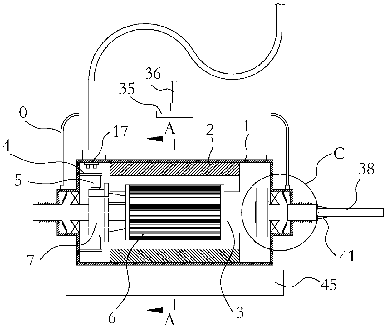
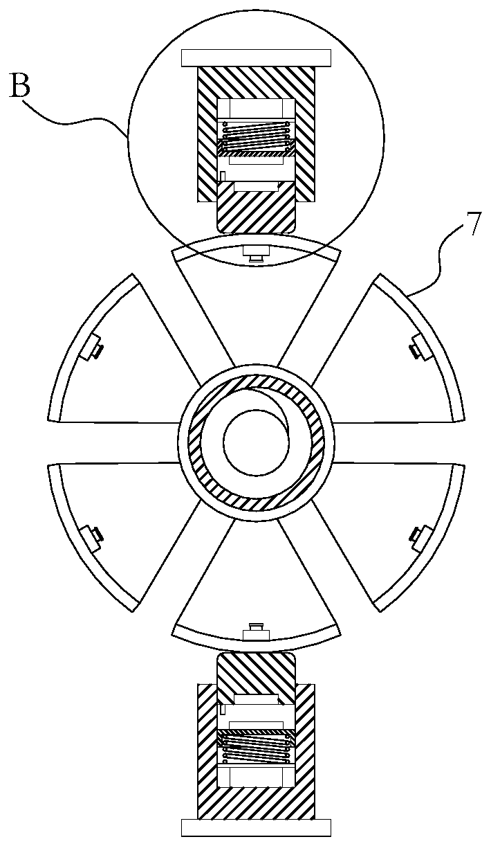
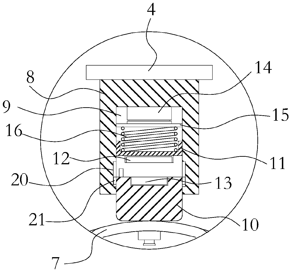
[0030] like Figure 1-10 The motor shown is the same as the conventional DC motor in that it also includes a casing 1 , a pair of stators 2 fixedly arranged on the inner wall of the casing 1 , and a rotating shaft 3 installed between the pair of stators 2 . A mounting bracket 4 is provided on the inner wall of the housing 1 corresponding to one end of the rotating shaft 3, such as figure 1 As shown in the figure, that is, the inner wall of the housing 1 at the left end of the rotating shaft 3 is provided with a mounting frame 4 , and a brush 5 is provided on the mounting frame 4 . A rotor 6 consisting of a magnetic core and an electromagnetic coil is arranged on a section of the rotating shaft 3 between the stators 2 , and the electromagnetic coil is wound on the magnetic core. After the rotor 6 is energized, the rotor 6 is affected by the magnetic force of the stator 2 and continues to rotate in the casing 1 . A commutator 7 is disposed on the rotating shaft 3 at a position...


PUM


Abstract

The invention relates to the technical field of motors, and provides a direct current motor with a constant voltage electric brush, wherein the direct current motor can guarantee stable pressure of the electric brush. The electric brush comprises a seat body fixedly arranged on an installation frame; a sliding hole extending in the length direction of the seat body is formed in the end face of theend, facing a commutator, of the seat body; a carbon brush matching the sliding hole is arranged in the outer end of the sliding hole; a driving block matching the sliding hole is further arranged inthe sliding hole; an electromagnet and a permanent magnet are arranged on the surface, opposite to a carbon brush, of the driving block; the electromagnet is opposite to the permanent magnet; and theelectromagnet and the permanent magnet repel each other in the power-on state. According to the invention, constant-voltage contact between the electric brush and the commutator can be guaranteed inthe true sense, the response speed is high, and control is flexible and convenient.

Description

technical field [0001] The invention relates to the technical field of motors, in particular to a DC motor with constant voltage brushes. Background technique [0002] DC motor is a type of motor widely used in daily production and life, usually including casing, stator, rotor, commutator, brush and other components. The stator usually adopts permanent magnet or directional electromagnetic coil group, which is fixedly installed in the casing. , which provides magnetic power to the rotor. The rotor is usually composed of several sets of electromagnetic coils and magnetic cores wound on it, and interacts with the stator during excitation to form a rotating force. The commutator is installed on the rotor, which is usually formed by a plurality of arc-shaped conductive sheets to form a ring, which is in conduction with the electromagnetic coil on the rotor, and is connected to the power source through the brush. The DC motor has the characteristics of good starting and speed r...

Claims


Application Information

Patent Timeline
IPC IPC(8): H02K23/66H02K13/10H02K5/14H02K5/18H02K9/06H01R39/24
CPCH01R39/24H02K5/14H02K5/18H02K9/06H02K13/10H02K23/66
Inventor 俞晓
Owner LESHAN DONGCHUAN MACHINERY
Why Eureka
Try Eureka