
A low frequency (LF) antenna control circuit

An antenna control and circuit technology, applied in electrical components, transmission systems, etc., can solve problems such as antenna misalignment, data transmission errors, carrier frequency deviation, etc.

Active Publication Date: 2020-08-25
NXP BV
View PDF7 Cites 0 Cited by
  • Summary
  • Abstract
  • Description
  • Claims
  • Application Information

AI Technical Summary

Problems solved by technology

Ideally, these antennas are tuned to the carrier frequency, however, in practical scenarios the resonant frequency deviates from the carrier frequency due to component spreading (deviation from nominal) and / or environmental reasons
These deviations can cause antenna misalignment, and misalignment can cause data transmission errors

Method used


Image

  • A low frequency (LF) antenna control circuit
  • A low frequency (LF) antenna control circuit

Examples


Embodiment Construction

[0014] Many well-known manufacturing steps, components, and connectors have been omitted or have not been described in detail in the description so as not to obscure the present disclosure.

[0015] The L-C antenna is used in passive keyless entry systems to radiate a low frequency magnetic field to establish communication between the car antenna and the second antenna in the car key. Note that the term "car" is often used. Those skilled in the art will appreciate that the embodiments described herein are applicable to any remote keyless locking and control system.

[0016] Ideally, these antennas are tuned to the carrier frequency, however, in practical situations, the resonant frequency of the antenna may deviate from the carrier frequency due to environmental reasons or aging of components (eg inductors, capacitors, etc.). In some examples, the car antenna communicates with the key fob antenna via an amplitude modulated on / off keying (OOK) method. Data sent via OOK can be...


PUM


Abstract

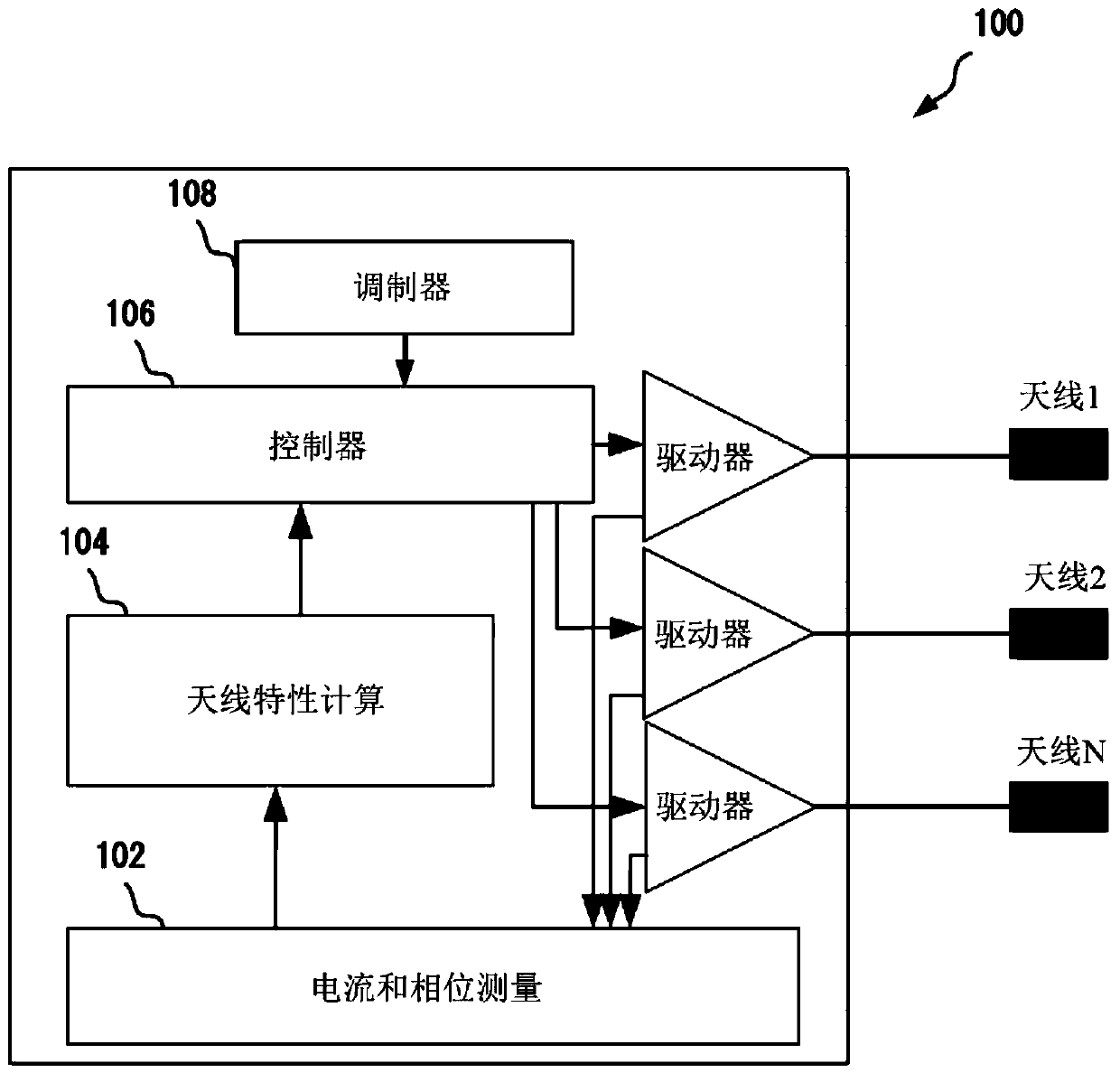
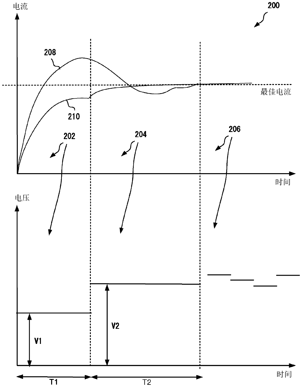
A low frequency (LF) antenna control circuit is disclosed. The LF antenna control circuit includes an antenna driver to drive an antenna, a current and phase measurement circuit to measure antenna current and signal phase, a modulator to modulate a signal to be transmitted via the antenna and a controller configured to drive the antenna through the antenna driver using a first fixed amplitude fora first time period, a second fixed amplitude for a second time period that is subsequent to the first time period and subsequent to the second time period, and subsequently, to drive the antenna using step up / down voltages based on the measured antenna current and signal phase. The signal included encoded bits of data to be transmitted.

Description

technical field [0001] The present invention relates to the field of automobiles, and more particularly, to a low-frequency antenna control circuit. Background technique [0002] An inductance-capacitance (L-C) antenna is used in a passive keyless entry system to radiate a low frequency magnetic field to establish communication between the vehicle antenna and a second antenna in the vehicle key. Ideally, these antennas are tuned to the carrier frequency, however, in practical scenarios the resonant frequency deviates from the carrier frequency due to component spreading (deviation from nominal) and / or environmental reasons. These deviations may cause misalignment of the antenna, and misalignment may cause data transmission errors. Contents of the invention [0003] This Summary is provided to introduce a selection of concepts in a simplified form that are further described below in the Detailed Description. This Summary is not intended to identify key features or essenti...

Claims


Application Information

Patent Timeline
IPC IPC(8): H04B1/04H04B1/74
CPCH04B1/04H04B1/745
Inventor 詹斯·弗莱施哈克尔赫尔曼纳斯·约翰内斯·埃芬
Owner NXP BV
Learn More