Chopping board side wall grooving equipment

A technology for grooving equipment and cutting boards, which is used in metal processing equipment, metal processing machinery parts, maintenance and safety accessories, etc., can solve the problems of time-consuming and labor-intensive, and it is difficult to always keep the cutting machine attached to the side wall of the cutting board.

Active Publication Date: 2020-08-28
吴燕灵
View PDF6 Cites 13 Cited by
  • Summary
  • Abstract
  • Description
  • Claims
  • Application Information

AI Technical Summary

Problems solved by technology

[0004] In order to overcome the disadvantages of manually grooving the side wall of the cutting board, which is time-consuming and labor-intensive, and it is not easy to keep the cutting machine close to the side wall of the cutting board, the technical problem of the present invention is to provide a cutting machine that can groove the side wall of the cutting board and improve the efficiency of slotting. , the cutting board side wall grooving equipment that ensures the same depth of the grooves opened by the cutting machine

Method used


Image

  • Chopping board side wall grooving equipment
  • Chopping board side wall grooving equipment
  • Chopping board side wall grooving equipment

Examples


Embodiment 1

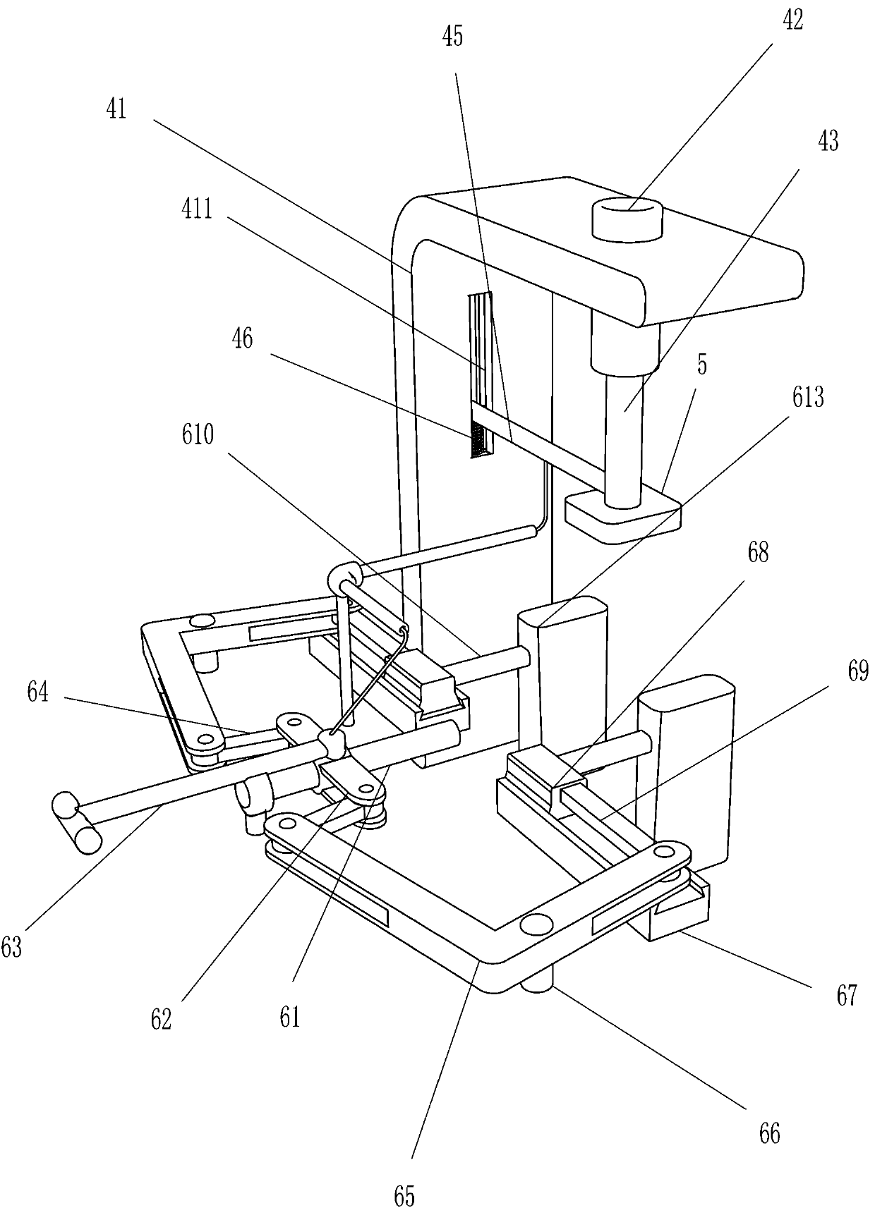
[0053] A cutting board side wall slotting device, such as figure 1 with Image 6 As shown, a cutting board side wall slotting equipment includes a base, a workbench, a cylindrical storage box, a lifting mechanism, a cutting machine, a clamping and rotating mechanism, a collection frame, an installation sleeve, a wire tube and a pull wire, and the base is equipped with Workbench, there is a groove in the middle of the right side of the workbench, and a cylindrical storage box is provided in the middle of the right side of the workbench. There are round holes on both sides of the cylindrical storage box. The cylindrical storage box is located directly above the groove. There is a lifting mechanism at the rear of the side, and a cutting machine is installed at the lower end of the front side of the lifting mechanism. The cutting machine is located directly above the cylindrical storage box, and the top of the workbench is equipped with a clamping and rotating mechanism. The hole...

Embodiment 2

[0056] A cutting board side wall slotting device, such as Figure 1-2 with Figure 5 As shown, preferably, the lifting mechanism includes an L-shaped frame, a cylindrical sleeve, a cylindrical rod, a first spring, a first connecting rod, and a second spring. There is a square groove, a cylindrical sleeve is provided on the top of the L-shaped frame, and a cylindrical rod is provided slidingly at the bottom of the cylindrical sleeve. A first spring is connected between the inner bottom of the cylindrical sleeve and the top of the cylindrical rod, and the cylindrical rod passes through the second spring. A spring, a first connecting rod is arranged between the bottom of the cylindrical rod and the square groove, the rear end of the first connecting rod is slidingly matched with the square groove, and a second spring is arranged between the rear end of the first connecting rod and the bottom of the square groove.

[0057] After starting the clamping and rotating mechanism, the c...

Embodiment 3

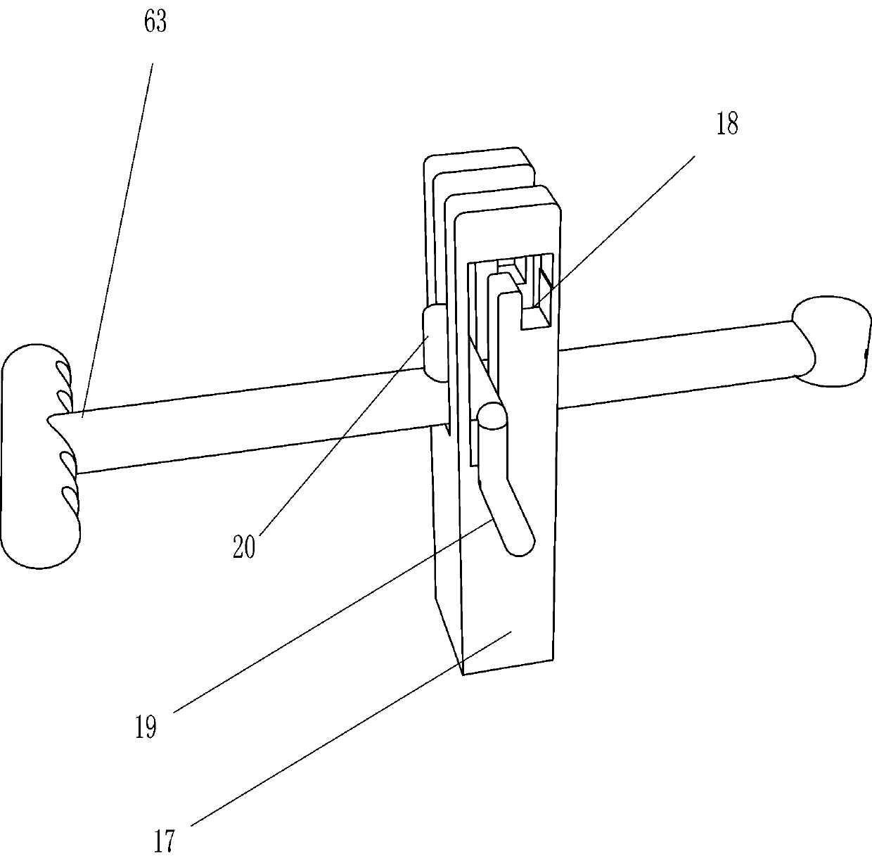
[0059] A cutting board side wall slotting device, such as Figure 1-4 As shown, the clamping and rotating mechanism includes guide rods, sliding rods, pull rods, first connecting rods, L-shaped rods, first rotating shafts, slide rails, sliders, second connecting rods, second connecting rods, sliding blocks, installation Plate, rotating shaft, circular splint, motor, fixed frame, clamping rod and round rod. There is a fixed frame in the middle of the left side of the top of the workbench. There is a guide rod between the middle part of the side and the left side of the cylindrical storage box. The guide rod is located on the right side of the fixed frame. The upper part of the guide rod is slidingly equipped with a pull rod. Located on the left side of the clamping rod, the top of the right end of the pull rod is connected to the left end of the pull wire. There are slide bars on both sides of the right end of the pull rod. The rotating type is equipped with L-shaped rods, and...


PUM


Abstract

The invention relates to grooving equipment, in particular to chopping board grooving equipment. According to the technical scheme, the chopping board side wall grooving equipment which can groove theside wall of a chopping board, improve the grooving efficiency and guarantee that the depths of grooves formed by a cutting machine are consistent is provided. According to the technical scheme, thechopping board grooving equipment comprises a base, a groove and a lifting mechanism, wherein the top of the base is provided with a workbench, the groove is formed in the middle of the side portion of the workbench, a cylindrical containing box is arranged at the position, over the groove, of the side portion of the workbench, round holes are formed in the two sides of the cylindrical containingbox, and the lifting mechanism is arranged on the side part, close to one side of the cylindrical placement box, of the workbench. According to the chopping board side wall grooving equipment, throughthe lifting mechanism, the cutting machine can automatically move up and down and is tightly attached to the side wall of the chopping board, it is guaranteed that the cutting machine makes tight contact with the side wall of the chopping board all the time before grooving work is completed, and it is guaranteed that the depths of the formed grooves are consistent; and through a clamping and rotating mechanism, the chopping board can be automatically clamped and driven to rotate.

Description

technical field [0001] The invention relates to a slotting device, in particular to an anvil board slotting device. Background technique [0002] At present, in order to hang and take the chopping board more conveniently, the manufacturer often creates a circle of grooves on the side wall of the chopping board, installs a steel ring in the groove, and sets a handle on the steel ring. It is cylindrical. In order to prevent it from rolling, workers need to fix the column cutting board tightly by hand. At the same time, in order to ensure the smooth opening of the groove, it is necessary to keep the cutting machine close to the side wall of the cutting board. If the cutting machine is misplaced, if the worker's strength is not properly controlled, the depth of the groove will be different, which will affect the beauty of the cutting board. [0003] In view of the above-mentioned shortcomings that the manual cutting of the side wall of the cutting board consumes a lot of energy...

Claims


Application Information

Patent Timeline
Patent Type & Authority Applications(China)
IPC IPC(8): B23D79/00B23Q7/00B23Q11/08
CPCB23D79/00B23Q7/00B23Q11/08
Inventor 吴燕灵
Owner 吴燕灵
Why Eureka
Try Eureka