Supercharge Your Innovation With Domain-Expert AI Agents!

Shaft fork machining clamp

A shaft fork and fixture technology, which is used in manufacturing tools, metal processing equipment, metal processing machinery parts, etc. The problem of low accuracy, etc., to achieve the effect of improving the position accuracy

Active Publication Date: 2020-08-28
TAIZHOU BAIDA ELECTRICAL APPLIANCE CO LTD
View PDF7 Cites 0 Cited by
  • Summary
  • Abstract
  • Description
  • Claims
  • Application Information

AI Technical Summary

Problems solved by technology

[0003] In the prior art, the blank of the shaft fork is molded by die-casting. The blank includes the bifurcation body and the main shaft body, which are clamped on the main shaft body to process the inner surface of the clamping groove and hole 2. Both hole 1 and hole 2 of the blank need Finishing, but the requirements for the outer dimensions of the shaft fork are not high. The manufacturing standard of the shaft fork requires that the axes between the first hole and the second hole are perpendicular to each other and intersect. Clamping the spindle rod for processing, because the outer surface of the blank has not been processed, the shape and size of the blank are quite different, resulting in the position accuracy of the processed hole 1 and hole 2 is not high, there are deficiencies to be improved

Method used


Image

  • Shaft fork machining clamp
  • Shaft fork machining clamp
  • Shaft fork machining clamp

Examples


Embodiment Construction

[0030] The present invention will be described in further detail below in conjunction with the accompanying drawings.

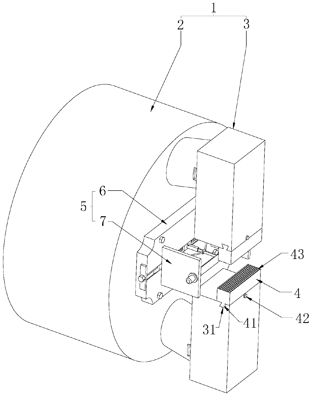
[0031] Such as figure 1 As shown, a jig for processing a shaft fork, including a cable-stayed chuck 1 (refer to the announcement number CN205341973U) and a positioning member 5 for defining the axial position of the shaft fork 15 hole 2 154, wherein the cable-stayed chuck 1 includes a chuck The frame 2 and the fixed claws 3 symmetrically arranged at both radial ends of the chuck frame 2, the fixed claws 3 include a shaft and abutting claws, the shaft slides through the chuck, and the sliding direction of the shaft is the same as that of the chuck frame 2. The axis is provided with an inclination angle; the blank is fixed on the positioning member 5, and the shaft slides so that the abutment claws are relatively close until the abutment claw clamps the blank, realizing the positioning and fixing of the blank before processing.

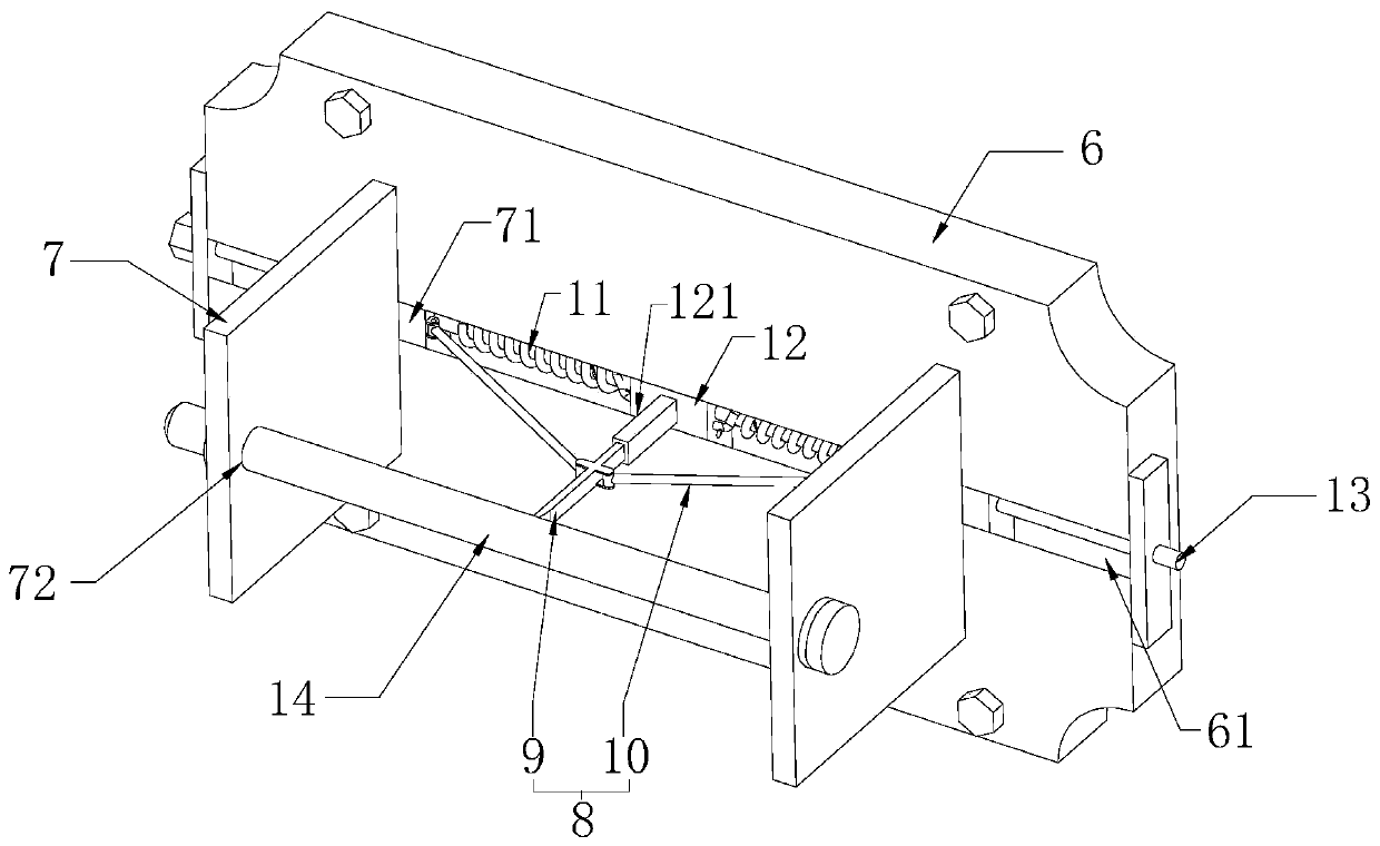
[0032] Such as figure 1 and ...


PUM


Abstract

The invention relates to the field of tools, and discloses a shaft fork machining clamp. The shaft fork machining clamp comprises a cable-stayed chuck and a positioning piece used for limiting the axis position of a second hole of a shaft fork, a clamping groove of the shaft fork is matched with an abutting plate in an embedded mode, and then the abutting plate slides on the contrary until the abutting plate extrudes the two opposite sides in the clamping groove; and the positioning shaft penetrates through the second hole of the shaft fork and an inserting hole in the abutting plate, a positioning shaft limits the movement of the axis of the shaft fork in the second hole, the abutting plate limits the movement of the shaft fork in the axis direction of the second hole, and finally a fixing claw moving relatively clamps and fixes the rotation of the shaft fork in the axis direction of the second hole, so that accurate positioning and fixing of the shaft fork are achieved, and the position precision of the first hole and the second hole in the shaft fork is improved.

Description

technical field [0001] The invention relates to the field of tooling, in particular to a jig for processing a shaft fork. Background technique [0002] The shaft fork includes a main shaft and a fork that fixes one end of the main shaft. The bifurcation includes a set of symmetrically arranged bifurcated plates, and a snap-fit ​​slot is formed between the bifurcated plates, and a hole is opened in the main shaft along its axis 1, and a hole 2 is opened on the bifurcation plate, and the axis of the hole 2 is perpendicular to and intersects with the axis of the hole 1. [0003] In the prior art, the blank of the shaft fork is molded by die-casting. The blank includes the bifurcation body and the main shaft body, which are clamped on the main shaft body to process the inner surface of the clamping groove and hole 2. Both hole 1 and hole 2 of the blank need Finishing, but the requirements for the outer dimensions of the shaft fork are not high. The manufacturing standard of the...

Claims


Application Information

Patent Timeline
IPC IPC(8): B23Q3/06
CPCB23Q3/062
Inventor 张启斌邵伯明尤国金许雄君徐顺永王强林程峰方甫金
Owner TAIZHOU BAIDA ELECTRICAL APPLIANCE CO LTD
Features
  • R&D
  • Intellectual Property
  • Life Sciences
  • Materials
  • Tech Scout
  • Unparalleled Data Quality
  • Higher Quality Content
  • 60% Fewer Hallucinations
Learn More