
Design method of laser particle analyzer optical system

A technology of laser particle size analyzer and optical system, which is applied in particle size analysis, scientific instruments, particle and sedimentation analysis, etc. It can solve the problems of low measurement accuracy and large difference in focus position, and achieve the effect of improving position accuracy

Inactive Publication Date: 2015-04-29
THE 3RD ACAD 8358TH RES INST OF CASC
View PDF8 Cites 3 Cited by
  • Summary
  • Abstract
  • Description
  • Claims
  • Application Information

AI Technical Summary

Problems solved by technology

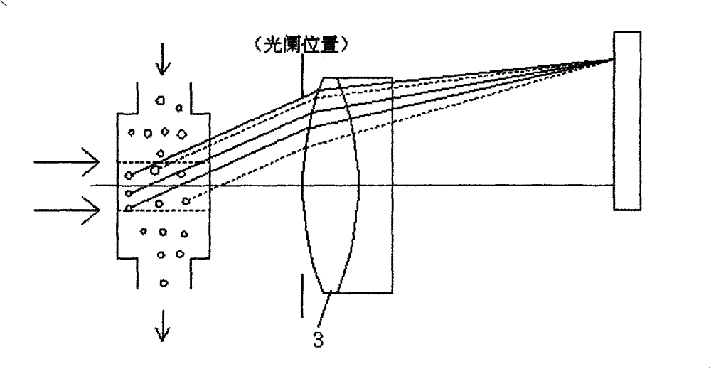
[0005] The technical problem to be solved by the present invention is: in the optical system of the laser particle size analyzer in the prior art, the position of the diaphragm is fixed on the front surface of the lens, resulting in particles

Method used


Image

  • Design method of laser particle analyzer optical system
  • Design method of laser particle analyzer optical system
  • Design method of laser particle analyzer optical system

Examples


Example Embodiment

[0019] The design method of the optical system of the laser particle size analyzer of the present invention will be introduced below with reference to the accompanying drawings and embodiments.

[0020] The optical system of the laser particle size analyzer of the present invention includes a diaphragm, a lens and a ring photodetector, which are arranged one after another along the optical path, and the diaphragm is zoomed in multiple positions within the range of the sample cell of the measurement window of the laser particle size analyzer. The light in the same direction scattered by the particles in the sample cell is focused on the same half ring of the ring photodetector with the smallest position difference.

[0021] When using the method of the present invention to design the optical system of the laser particle size analyzer, it is necessary to control the positions of the chief ray, upper ray, lower ray, left ray, and right ray of each field of view on the ring photodetecto...


PUM


Abstract

The invention belongs to the technical field of laser particle analyzer optical systems, and particularly relates to a design method of a laser particle analyzer optical system. The laser particle analyzer optical system designed with the method comprises a diaphragm, a lens and an annular photoelectric detector which are sequentially arranged front and back in the light path direction, and multi-position zooming design is adopted for the diaphragm during optical system design. The technical problem of low measurement accuracy of the laser particle analyzer optical system in the prior art is solved. According to the method, during optical system design, multi-position zooming is adopted for the diaphragm in a sample cell range, positions of light, scattered in different positions, located in a receiver are comprehensively considered during aberration correction, and the positional accuracy after parallel beams scattered by particles in the same direction pass the lens is effectively improved.

Description

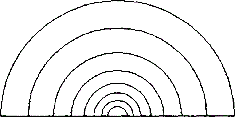
technical field [0001] The invention belongs to the technical field of laser particle size meter optical system design, and in particular relates to a laser particle size meter optical system design method. Background technique [0002] Such as figure 1 As shown, the laser particle size analyzer is mainly composed of three parts: the transmitting component, the measuring window and the receiving component. The emission component is composed of a light source and a beam shaping optical system. The laser beam emitted by the laser is focused, low-pass filtered and collimated to provide monochromatic parallel illumination light for the laser particle size analyzer; the measurement window is used to make the measured sample in a completely dispersed suspension The laser particle size analyzer passes through the measurement area in order to obtain the particle size information of the sample; the receiving component is a key component of the optical system of the laser particle si...

Claims


Application Information

Patent Timeline
IPC IPC(8): G01N15/02
Inventor 于双双杜吉史宣
Owner THE 3RD ACAD 8358TH RES INST OF CASC
Learn More