
Imaging apparatus and position detection method

Inactive Publication Date: 2018-05-24
OM DIGITAL SOLUTIONS CORP
View PDF0 Cites 3 Cited by
  • Summary
  • Abstract
  • Description
  • Claims
  • Application Information

AI Technical Summary

Benefits of technology

The patent is about an improved imaging apparatus and position detection method that can make it easier to accurately locate things.

Problems solved by technology

This means that if an enlarged image is displayed when changing setting distance, coarseness of image movement is noticeable.

Method used


Image

  • Imaging apparatus and position detection method
  • Imaging apparatus and position detection method
  • Imaging apparatus and position detection method

Examples


Embodiment Construction

[0027]In the following, preferred embodiments of the present invention will be described in detail in accordance with the attached drawings. It should be noted that in the following description, an example is given of a digital camera as the imaging apparatus, and description is given for a case where an interchangeable lens is used with this camera. However, the present invention is not limited to this and may be applied widely as long as it is with a device that detects position in accordance with rotation operation or linear operation etc. It should be also noted that the imaging apparatus of this embodiment has a lens that is movable in an optical axis direction, provided within a lens barrel that includes a photographing lens.

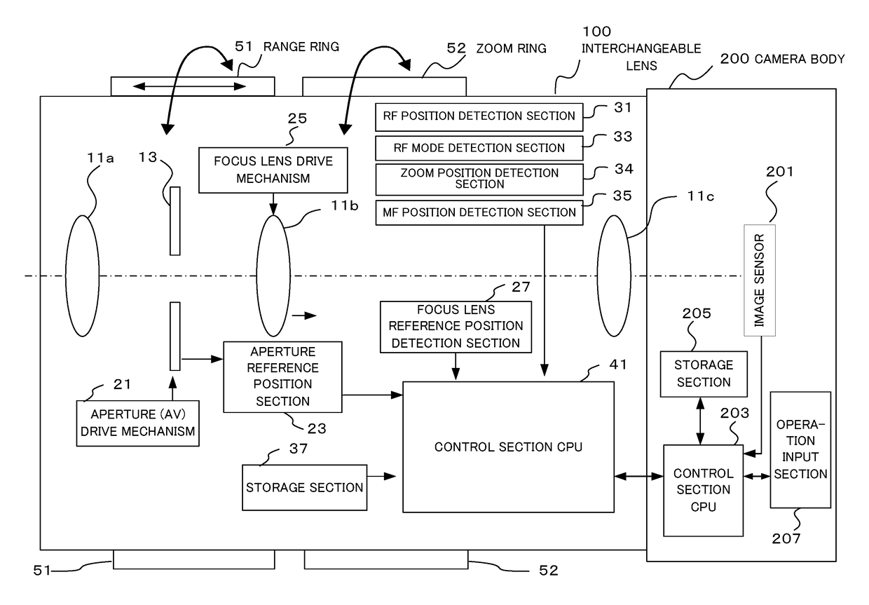
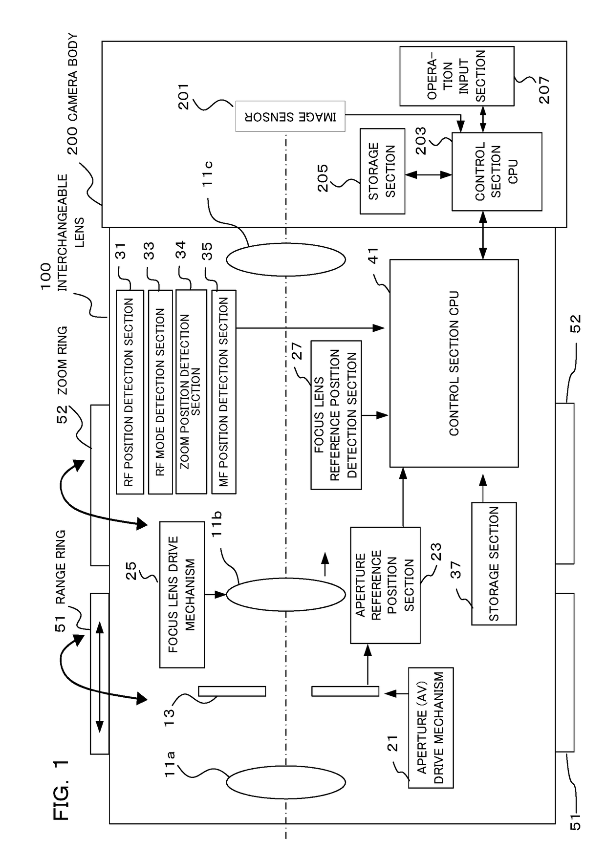
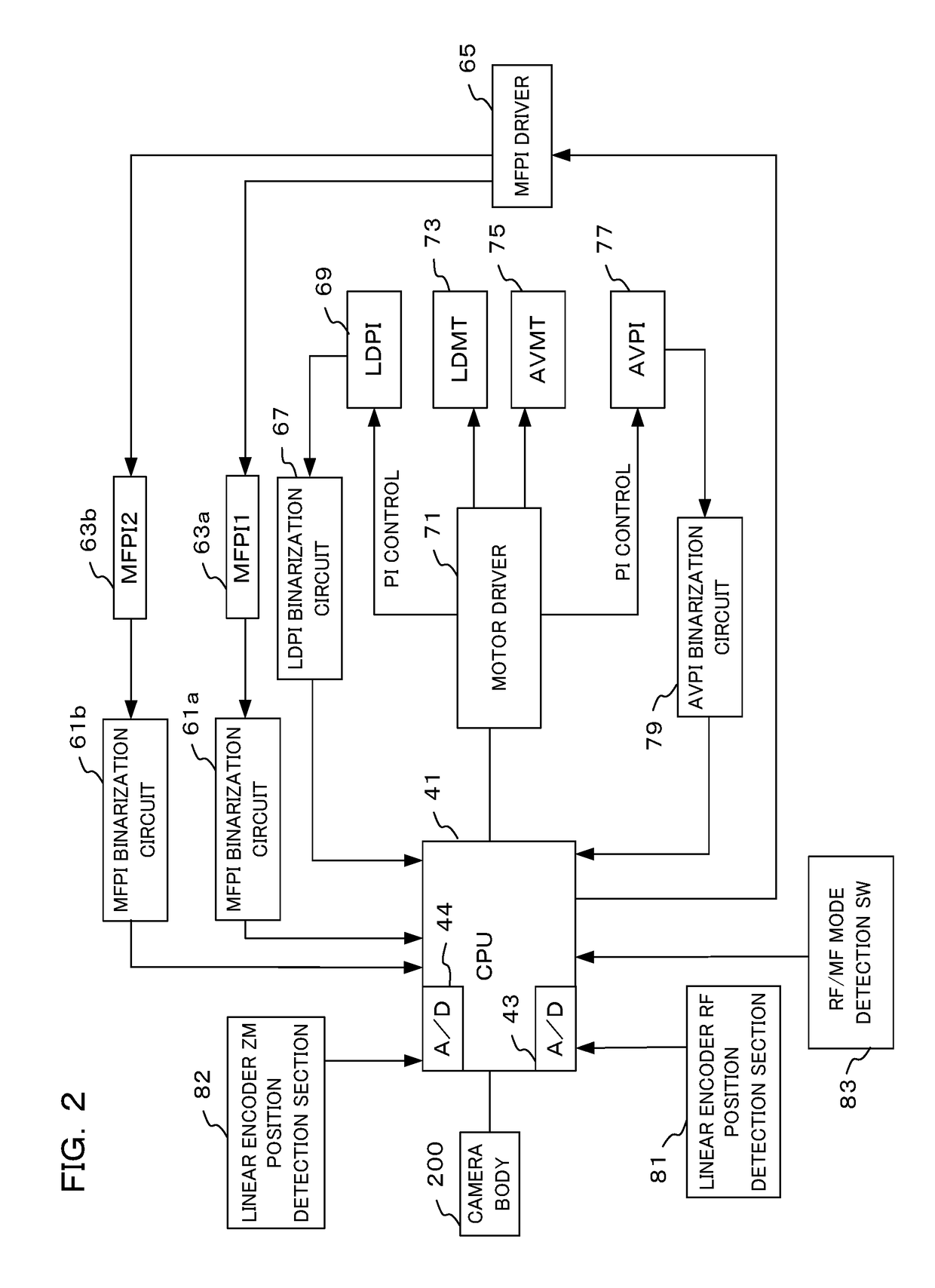
[0028]FIG. 1 is a block diagram showing the structure of a camera of one embodiment of the present invention, and FIG. 2 is a block diagram showing the electrical structure of this camera. This camera comprises an interchangeable lens 100 and a camera body...


PUM


Abstract

An imaging apparatus, comprising a detection element that outputs analog signals in accordance with position of the operation member, an A / D converter that converts the analog signals to digital values, and a controller that detects position of the operation member, wherein the controller, when it is determined that the operation member is stopped, compares an average value of a first number of digital values with a first threshold value, and determines that the operation member is moving if it has been determined that the average value is greater than the first threshold value, and when it is determined that the operation member is moving, compares a difference between a newest digital value and a digital value that was acquired a second number previously with a second threshold value, and determines that the operation member has stopped if it is determined that the difference is smaller than the second threshold value.

Description

CROSS-REFERENCE TO RELATED APPLICATIONS[0001]Benefit is claimed, under 35 U.S.C. § 119, to the filing date of prior Japanese Patent Application No. 2016-224702 filed on Nov. 18, 2016. This application is expressly incorporated herein by reference. The scope of the present invention is not limited to any requirements of the specific embodiments described in the application.BACKGROUND OF THE INVENTION1. Field of the Invention[0002]The present invention relates to an imaging apparatus and a position detection method that convert an electrical analog change, such as voltage change, to a digital value using an A / D converter, and detect position based on this AD value.2. Description of the Related Art[0003]As a position detection device that detects position using electrical analog change, there is known a position detection device that detects rotation operation position of an operation ring of a lens barrel, for example. Specifically, since a voltage that is detected using an encoder is...

Claims


Application Information

Patent Timeline
IPC IPC(8): G02B7/28H04N5/232G02B7/04
CPCG02B7/282H04N5/23212H04N5/23245H04N5/23296G02B7/04H04N23/675H04N23/667H04N23/69
Inventor OKAWA, SATOSHI
Owner OM DIGITAL SOLUTIONS CORP
Learn More