Novel stranding machine

A twisting machine, a new type of technology, applied in spinning machines, continuous winding spinning machines, textiles and papermaking, etc., can solve the problems of increasing energy consumption and difficulty in adapting, so as to reduce energy consumption and improve twisting efficiency Effect

Pending Publication Date: 2020-08-28
株洲宏远机械制造有限责任公司
View PDF0 Cites 0 Cited by
  • Summary
  • Abstract
  • Description
  • Claims
  • Application Information

AI Technical Summary

Problems solved by technology

[0002] Existing stranding machines are generally composed of motors, transmissions, main shafts, flywheels, cradle frames, pay-off I-shaped wheels, and take-up I-shaped wheels. The two flywheel discs are set on the two main shafts, and the outer diameter edge of the flywheel discs is equipped with wire wheels, and the cradle frame is set at the distance between the two main shafts and connected with the two main shafts; The hollow hole of the main shaft is then passed through the main shaft pulley and the wire passing wheel respectively to carry out the hollow hole of the other main shaft, and then directly reaches the take-up I-shaped wheel to complete the twisting; during the working process of such a stranding machine, the main shaft rotates once , only twisted twice, such twisting speed is difficult to meet the needs of high-speed production; and if the twisting speed needs to be increased, it can only rely on increasing the spindle speed, which will undoubtedly greatly increase energy consumption

Method used


Image

  • Novel stranding machine
  • Novel stranding machine
  • Novel stranding machine

Examples


Embodiment Construction

[0018] The present invention will be further described below in conjunction with the accompanying drawings and embodiments. In describing the present invention, it should be understood that the terms "center", "longitudinal", "transverse", "upper", "lower", "front", "rear", "left", "right", " Orientations or positional relationships indicated by "vertical", "horizontal", "top", "bottom", "inner", "outer", "axial", "radial", etc. are based on the orientation or position shown in the drawings The relationship is only for the convenience of describing the present invention and simplifying the description, but does not indicate or imply that the referred device or element must have a specific orientation, be constructed and operated in a specific orientation, and thus should not be construed as a limitation of the present invention.

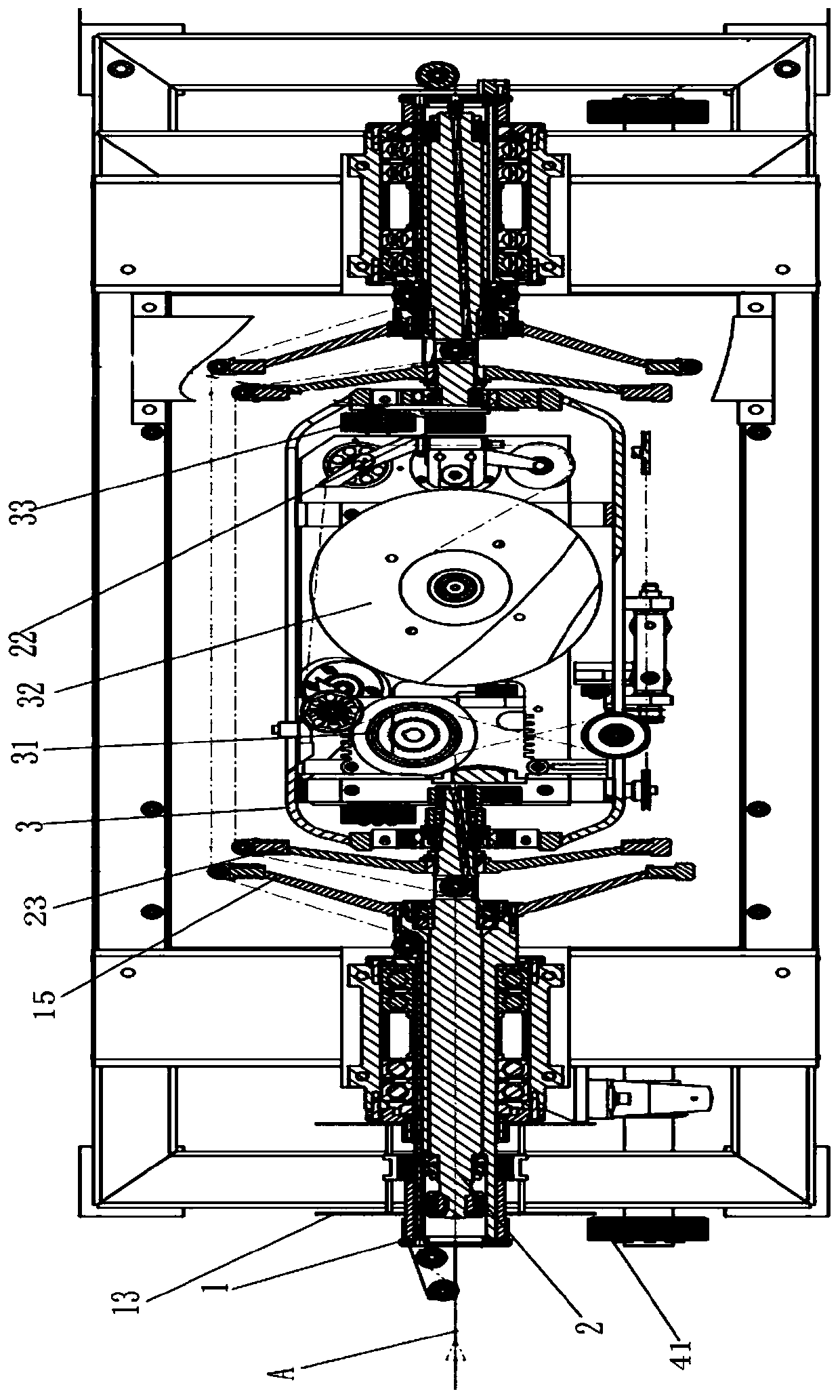
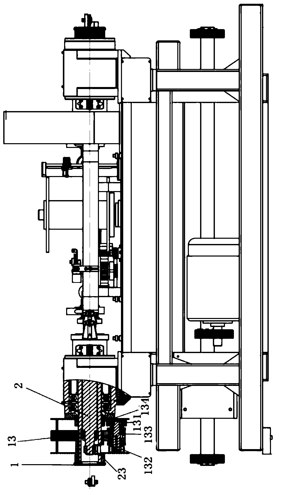
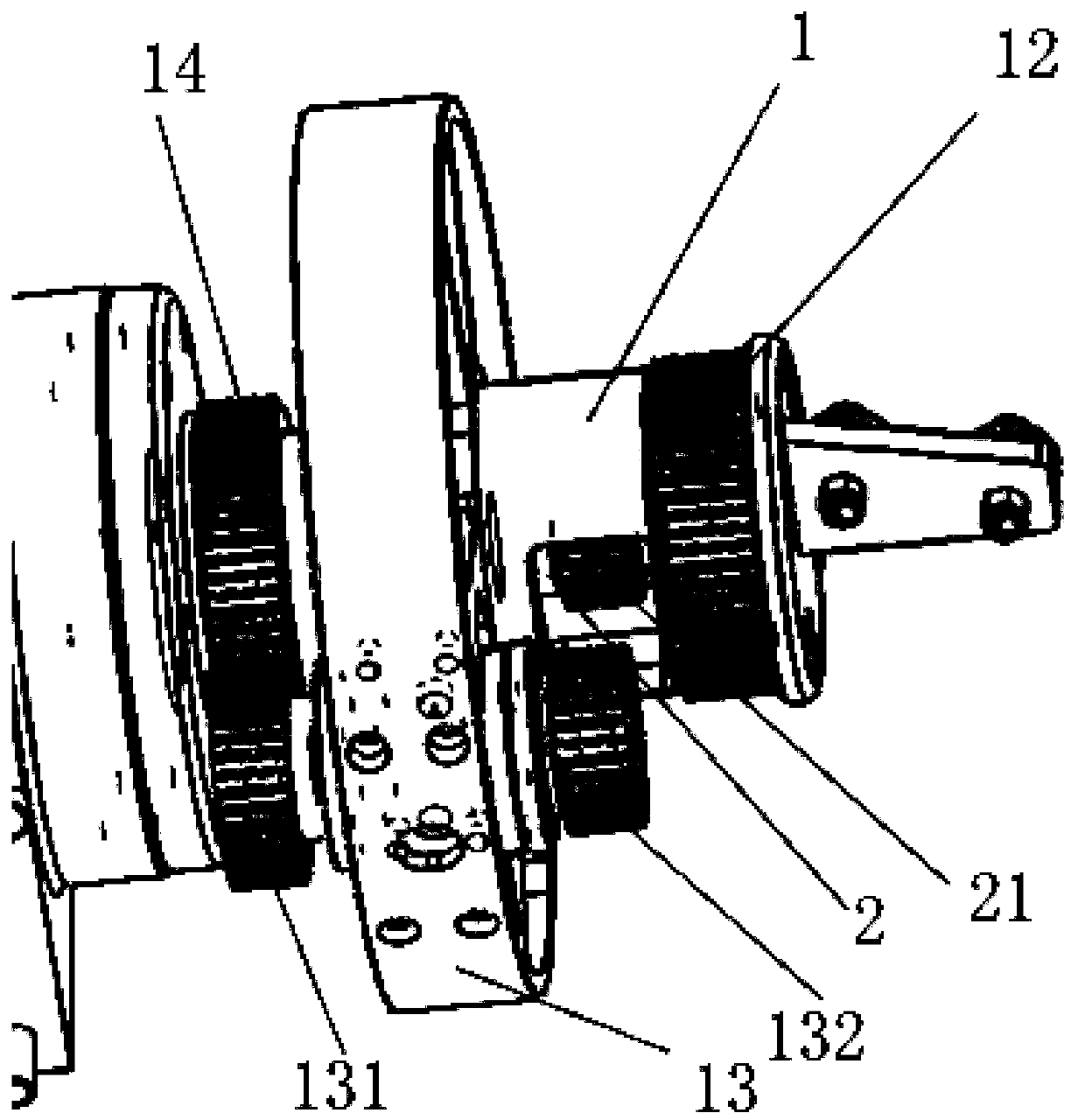
[0019] Such as Figure 1-4 Shown, the present invention proposes a kind of novel twisting machine, and this twisting machine mainly is made up of m...


PUM


Abstract

The invention provides a novel stranding machine. The novel stranding machine comprises a main machine frame, a motor, a transmission device, a pair of main shafts oppositely arranged along a same axis, a cradle frame fixed between the two main shafts, a paying-off device and a taking-up device. The novel stranding machine is characterized in that the main shafts include an inner shaft and an outer shaft which are arranged coaxially, and a reversing device is disposed on the main shaft at one end; the reversing device comprises a rotary disk fixed to the outer shaft, and a first intermediate wheel and a second intermediate wheel which are in pair and are coaxial with each other are arranged on the rotary disk; the first intermediate wheel is in flexible transmission with a first transmission wheel fixed to an outer shaft shell, and the second intermediate wheel is in flexible transmission with a second transmission wheel fixed to the inner shaft; the ends of the outer shaft and the inner shaft are connected with independent flywheel disks and wire wheels; and hollow holes allowing a wire to pass through are formed in the outer shaft and the inner shaft. Compared with an existing stranding machine, the novel stranding machine can improve the stranding efficiency by one time under the same rotation speed condition; and the same stranding efficiency can be achieved under the condition that the rotation speed of the main shafts is decreased by one time, and energy consumption is reduced.

Description

technical field [0001] The invention relates to the technical field of twisting machines, in particular to a novel twisting machine capable of realizing one-turn four-twisting. Background technique [0002] Existing stranding machines are generally composed of motors, transmissions, main shafts, flywheels, cradle frames, pay-off I-shaped wheels, and take-up I-shaped wheels. The two flywheel discs are set on the two main shafts, and the outer diameter edge of the flywheel discs is equipped with wire wheels, and the cradle frame is set at the distance between the two main shafts and connected with the two main shafts; The hollow hole of the main shaft is then passed through the main shaft pulley and the wire passing wheel respectively to carry out the hollow hole of the other main shaft, and then directly reaches the take-up I-shaped wheel to complete the twisting; during the working process of such a stranding machine, the main shaft rotates once , only twisted twice, such a...

Claims


Application Information

Patent Timeline
IPC IPC(8): D01H1/10D01H1/241D01H1/242
CPCD01H1/10D01H1/241D01H1/242
Inventor 李文卷
Owner 株洲宏远机械制造有限责任公司
Why Eureka
Try Eureka