Moving target positioning method for distributed MIMO radar system

A technology for radar positioning and moving targets, which can be used in radio wave measurement systems, reflection/re-radiation of radio waves, and use of re-radiation, etc., and can solve problems such as performance degradation.

Pending Publication Date: 2020-08-28
UNIT 63892 OF PLA
View PDF1 Cites 3 Cited by
  • Summary
  • Abstract
  • Description
  • Claims
  • Application Information

AI Technical Summary

Problems solved by technology

When the measurement error is small, it can reach CRLB, but when the measurement error is large, the performance drops more seriously

Method used


Image

  • Moving target positioning method for distributed MIMO radar system
  • Moving target positioning method for distributed MIMO radar system
  • Moving target positioning method for distributed MIMO radar system

Examples


Embodiment Construction

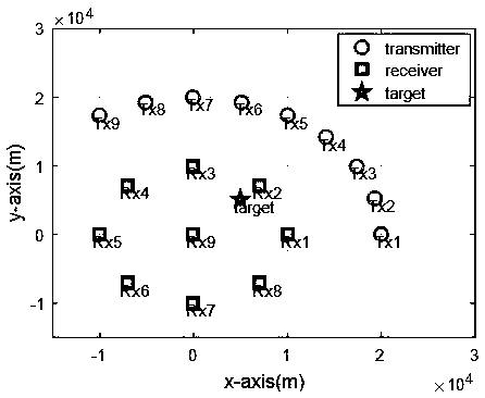
[0090] Such as figure 1 As shown in Figure 3(b), a distributed MIMO radar system moving target positioning method includes:

[0091] 1. Distributed MIMO radar positioning scenario:

[0092] Suppose there are M transmitting units, N receiving units, and one target in the scene; the target’s position x=[x,y] T is the parameter to be estimated;

[0093] The position of the transmitting unit m is The position of receiving unit n is Then, the distance from the target to the transmitting unit m can be expressed as:

[0094]

[0095] In the formula, ||*|| represents the 2-norm; similarly, the distance from the target to the receiving unit n is:

[0096]

[0097] By definition, the BRs corresponding to transmitting unit m and receiving unit n are respectively

[0098]

[0099] Since the BR observation is nonlinear with respect to the target position, it is difficult to directly obtain the algebraic solution of the target position; in order to linearize the BR observat...


PUM


Abstract

The invention relates to the technical field of distributed radar systems, and discloses a moving target positioning method for a distributed MIMO radar system, which takes a bistatic distance (BR) asan observed quantity, and comprises a distributed MIMO radar positioning scene, and constraining overall least square positioning; and the method comprises the following steps: constructing an auxiliary vector, performing linearization processing on an observation equation of a nonlinear bistatic distance, establishing a positioning problem as a constrained total least square model, and solving the model by adopting a Newton iteration method, thereby obtaining target position estimation. According to the method, BR observation is utilized to estimate the position and the speed of the target,no additional requirements are required for the number of the transmitting units and the number of the receiving units, errors existing in an equation coefficient matrix and a data vector are avoided,and compared with an existing BR positioning method, the method has remarkable advantages and superiority in the aspect of positioning precision when the measurement error is large.

Description

technical field [0001] The invention relates to the technical field of a distributed MIMO radar system, in particular to a method for locating a moving target in a distributed MIMO radar system. Background technique [0002] Distributed radar adopts a separate transceiver structure, each pair of transmitting and receiving units forms an independent bistatic system to observe the target, and then transmits all the echo results to the fusion center for signal or information fusion processing, so as to obtain the target position, information such as speed. Compared with traditional radar, it has significant advantages in improving target detection performance, dealing with slow targets, and improving positioning accuracy. [0003] Time delay is a common parameter for moving target location in distributed MIMO radar. The delay observation directly corresponds to the sum of propagation distances of the signal from the transmitting unit to the receiving unit after being reflecte...

Claims


Application Information

Patent Timeline
Patent Type & Authority Applications(China)
IPC IPC(8): G01S13/46G01S13/58
CPCG01S13/46G01S13/58
Inventor 朱健东李坤王满喜戴幻尧乔会东陈冬冬刘海业崔新风
Owner UNIT 63892 OF PLA
Why Eureka
Try Eureka