A waveguide to coaxial converter

A waveguide coaxial and converter technology, applied to waveguide devices, circuits, connecting devices, etc., can solve the problems of unavoidable assembly errors, time and effort, and difficulty in reaching the standing wave index, so as to improve installation accuracy and improve Standing wave performance, save the effect of debugging

Active Publication Date: 2022-07-15
BEIJING INST OF RADIO MEASUREMENT
View PDF5 Cites 0 Cited by
  • Summary
  • Abstract
  • Description
  • Claims
  • Application Information

AI Technical Summary

Problems solved by technology

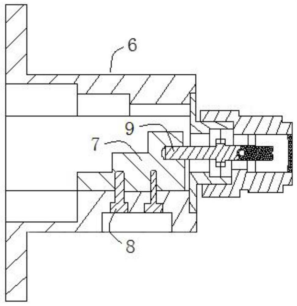
In addition, the matching block 7 is processed independently. Although the processing accuracy of the matching block 7 can be ensured, when the matching block 7 is assembled in the waveguide cavity, there are assembly errors and it is difficult to avoid assembly errors, so that the standing wave index of the waveguide coaxial converter Generally, the difference in the horizontal direction of the C-band is 0.1mm, and the standing wave influence is about 0.05-0.15, and the higher the frequency, the more obvious it is. Moreover, it is difficult to achieve a good Standing wave index, and debugging requires more time and effort

Method used


Image

  • A waveguide to coaxial converter
  • A waveguide to coaxial converter
  • A waveguide to coaxial converter

Examples


Embodiment Construction

[0031]In order to make the objectives, technical solutions and advantages of the present application clearer, the embodiments of the present application will be further described in detail below with reference to the accompanying drawings.

[0032] In order to be able to understand the above objects, features and advantages of the present invention more clearly, the present invention will be further described in detail below with reference to the accompanying drawings and specific embodiments. It should be noted that the embodiments of the present application and the features in the embodiments may be combined with each other in the case of no conflict.

[0033] Many specific details are set forth in the following description to facilitate a full understanding of the present invention. However, the present invention can also be implemented in other ways different from those described herein. Therefore, the protection scope of the present invention is not limited by the specific...


PUM


Abstract

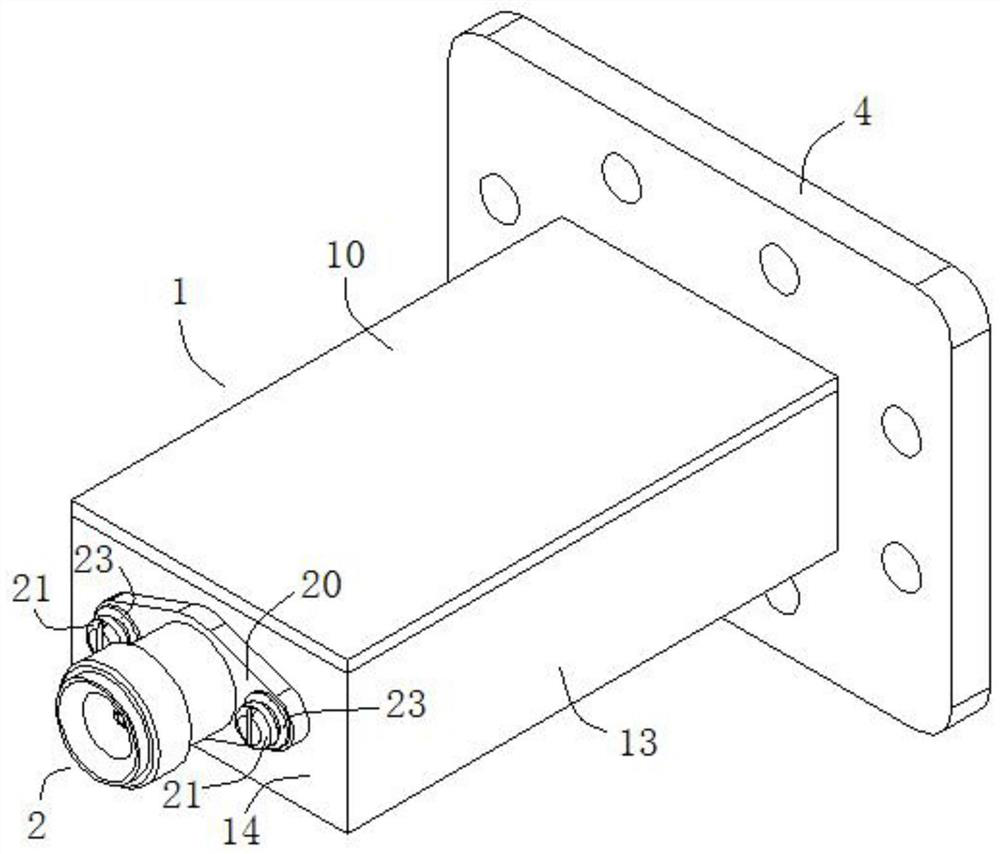
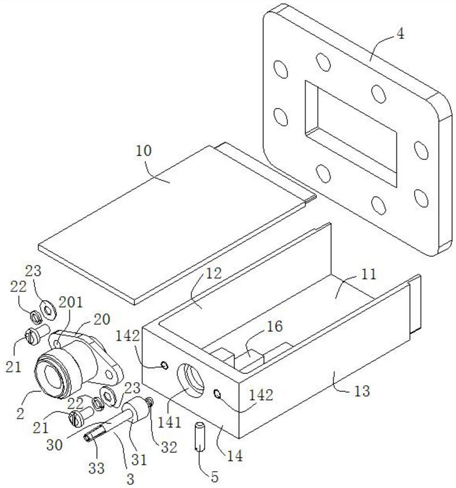
The invention discloses a waveguide coaxial converter, which belongs to the technical field of waveguide coaxial conversion equipment. It comprises: a waveguide body, the upper side is the broad side of the upper waveguide, the lower side is the broad side of the lower waveguide, the left and right sides are the narrow side of the left waveguide and the narrow side of the right waveguide, the front side is the end face of the waveguide, and the back side is open to form the waveguide port, A waveguide cavity is formed in the waveguide body; an impedance matching block is located in the waveguide cavity and a gap is formed between its front end face and the inner side wall of the waveguide end face. The impedance matching block is connected to the broad side of the lower waveguide, and the impedance matching block, the end face of the waveguide and the lower The broad side of the waveguide is integrally connected or formed by integral processing; the coaxial joint is installed on the end face of the waveguide, the coaxial joint includes a coaxial inner conductor, and the end face of the waveguide is provided with a through hole, and one end of the coaxial inner conductor passes through the through hole and is connected with the impedance. The matching block is connected, and the coaxial inner conductor is provided with a matching convex part which forms a gap 2 with the inner side wall of the end face of the waveguide. The waveguide-to-coaxial converter of the present invention can overcome assembly errors and improve standing wave performance.

Description

technical field [0001] The invention relates to the technical field of waveguide-coaxial conversion equipment, in particular to a waveguide-coaxial converter. Background technique [0002] Waveguide to coaxial converters are widely used in radar, communication equipment and other equipment to realize low-loss transition of microwave signals from waveguide system to coaxial system or from coaxial system to waveguide system. At present, the existing waveguide-to-coaxial converter structures such as figure 1 As shown, a matching block 7 is installed in the waveguide cavity in the waveguide 6, and then connected to the matching block 7 through pins 9. Usually, the matching block 7 is formed by processing first, and then the matching block 7 is fixed in the waveguide cavity through screws 8. , In order to ensure the standing wave performance of the waveguide coaxial converter and avoid short circuit, the gap formed between the matching block 7 and the inner wall of the front sid...

Claims


Application Information

Patent Timeline
Patent Type & Authority Patents(China)
IPC IPC(8): H01P5/10H01P5/103
CPCH01P5/10H01P5/103
Inventor 朱柯斌王建国
Owner BEIJING INST OF RADIO MEASUREMENT
Why Eureka
Try Eureka