Underground magnetic signal receiving device and receiving method based on Hall effect
A Hall effect and receiving device technology, applied in the field of underground magnetic signal receiving devices based on the Hall effect, can solve the problems of difficult adjustment of receiving sensitivity and frequency adjustment of receiving information, and achieve good anti-interference effect and improved accuracy
- Summary
- Abstract
- Description
- Claims
- Application Information
AI Technical Summary
Problems solved by technology
Method used
Image
Examples
Embodiment 1
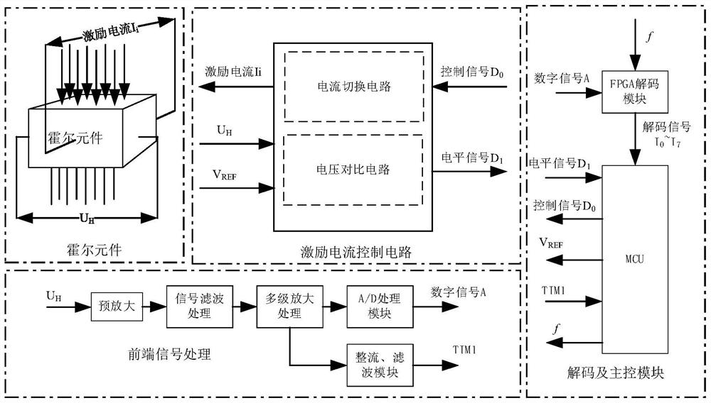
[0044] Embodiment 1: see Figure 1 to Figure 5 , a kind of underground magnetic signal receiving device based on Hall effect, comprises Hall element, FPGA decoding circuit and MCU, and described Hall element is used for excitation current I i Under the excitation of , it receives the magnetic signal and outputs the Hall voltage signal U H , after being decoded by the FPGA decoding circuit, it is sent to the MCU, which also includes a voltage comparison circuit, a current switching circuit, and a front-end signal processing circuit;
[0045] The output terminal of the Hall element is divided into two circuits, one is connected to the input terminal of the voltage comparison circuit, and the other is connected to the input terminal of the front-end signal processing circuit, which is used to connect U H respectively sent to the voltage comparison circuit and the front-end signal processing circuit;
[0046] The front-end signal processing circuit is used to U H Rectify and fi...
Embodiment 2
[0061] Example 2: see Figure 1 to Figure 5 , this embodiment is based on embodiment 1. The device of the underground magnetic signal receiving device based on the Hall effect is the same as embodiment 1, and also includes:
[0062] The front-end signal processing circuit includes a sequentially connected pre-amplification circuit, a signal filter processing circuit, and a multi-stage amplification processing circuit for processing the Hall voltage signal U H Prevent large, filter out power frequency interference signals, and further amplify the output; the output terminals of the multi-stage amplification processing circuit are respectively connected to the A / D processing module and the rectification and filtering module, wherein the A / D processing module is used to convert the signal of the amplified output The digital signal is sent to the FPGA, and the rectification and filtering module is used to convert the amplified output into a square wave and send it to the MCU to c...
Embodiment 3
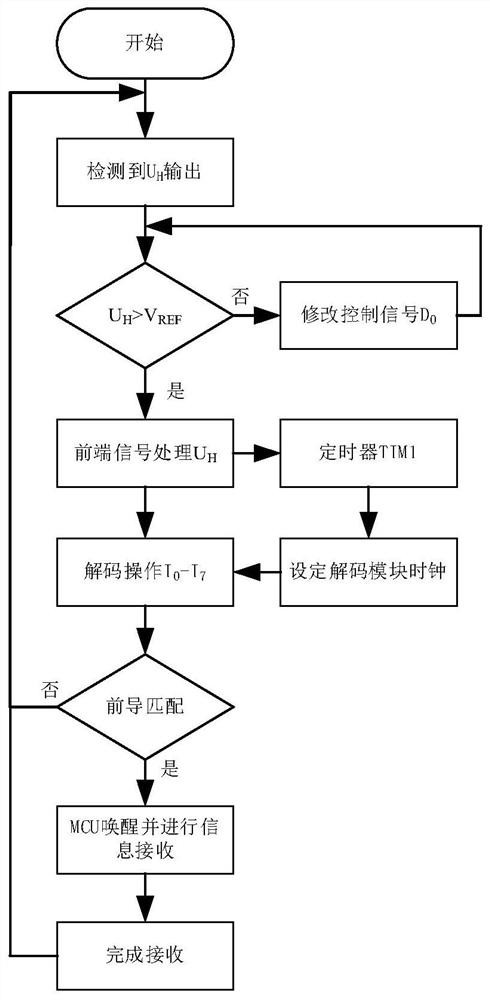
[0065] Embodiment 3: see Figure 1 to Figure 5 , the present embodiment provides a method for receiving an underground magnetic signal receiving device based on the Hall effect, a method for installing an underground magnetic signal receiving device based on the Hall effect, comprising the following steps:
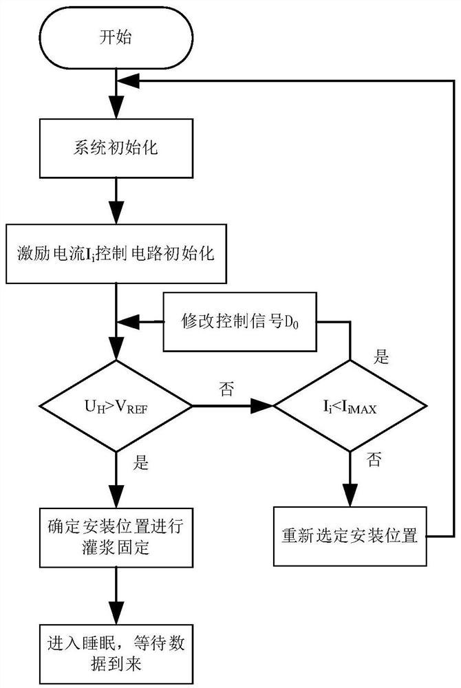
[0066] (1) Establish an underground magnetic signal receiving device based on the Hall effect, and preset the reference voltage V in the MCU REF and control signal D 0 ;
[0067] (2) Select an area to be tested for drilling, the aperture size is slightly larger than the size of the device, and place the device in the drill hole;
[0068] (3) Adjust the installation position, the specific method is the same as step (3) of embodiment 1; during the operation, I may appear i =I iMAX when U H still less than V REF In this case, it is necessary to re-select the location for installation. Finally, this step ensures that a suitable location can be selected, so that I i iMAX...
PUM
 Abstract
Description
Claims
Application Information
 - R&D
- Intellectual Property
- Life Sciences
- Materials
- Tech Scout
- Unparalleled Data Quality
- Higher Quality Content
- 60% Fewer Hallucinations
Browse by: Latest US Patents, China's latest patents, Technical Efficacy Thesaurus, Application Domain, Technology Topic, Popular Technical Reports.
© 2025 PatSnap. All rights reserved.Legal|Privacy policy|Modern Slavery Act Transparency Statement|Sitemap|About US| Contact US: help@patsnap.com


