
Patsnap Eureka
For R&D, Patsnap Eureka makes reading and utilizing patents & technical documents easy.
Patsnap Eureka AIR
Designed for self-driven R&D workflows. Generate viable solutions, solve complex R&D challenges, empower your innovation with AI.

Patsnap Eureka Materials
Designed for material experts only. Revolutionize your material R&D, from search, analyze, to developing new materials.

TechResearch
Generate reliable direction feasibility study reports for your R&D in just a few steps.

TechSeek
Discover and master advanced knowledge NOW. Basics, ideas, possibilities, all at once.

TechMind
As an expert in R&D Theories, TechMind can generates customized viable solutions instantly.

TechRisk
Analyze your overall solution with one click, know your potential R&D risks in advance.

TechMonitor
Get weekly tech updates, stay abreast of the latest tech innovations and key insights.
Electrical switching device
An electrical switch, switch technology, applied in the direction of switchgear, electric switch, switchgear setting, etc., can solve problems such as affecting operation
- Summary
- Abstract
- Description
- Claims
- Application Information
AI Technical Summary
Problems solved by technology
Method used
Image

Examples
Embodiment Construction
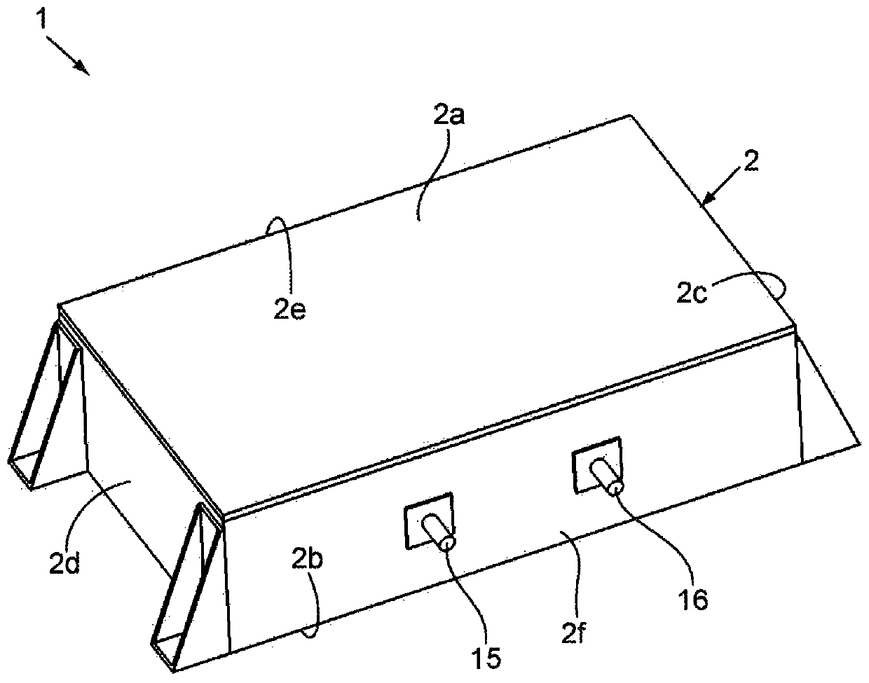
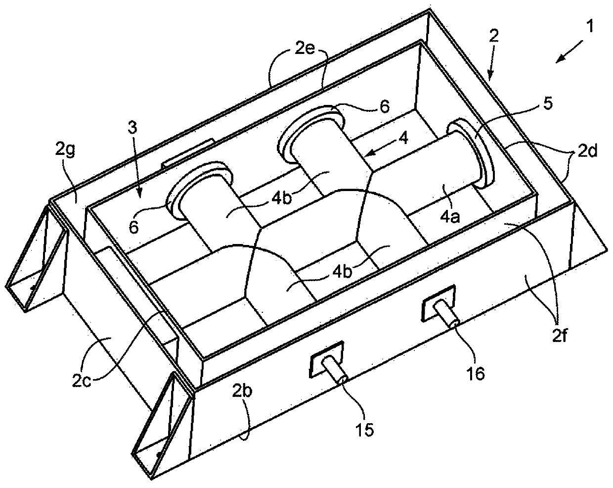
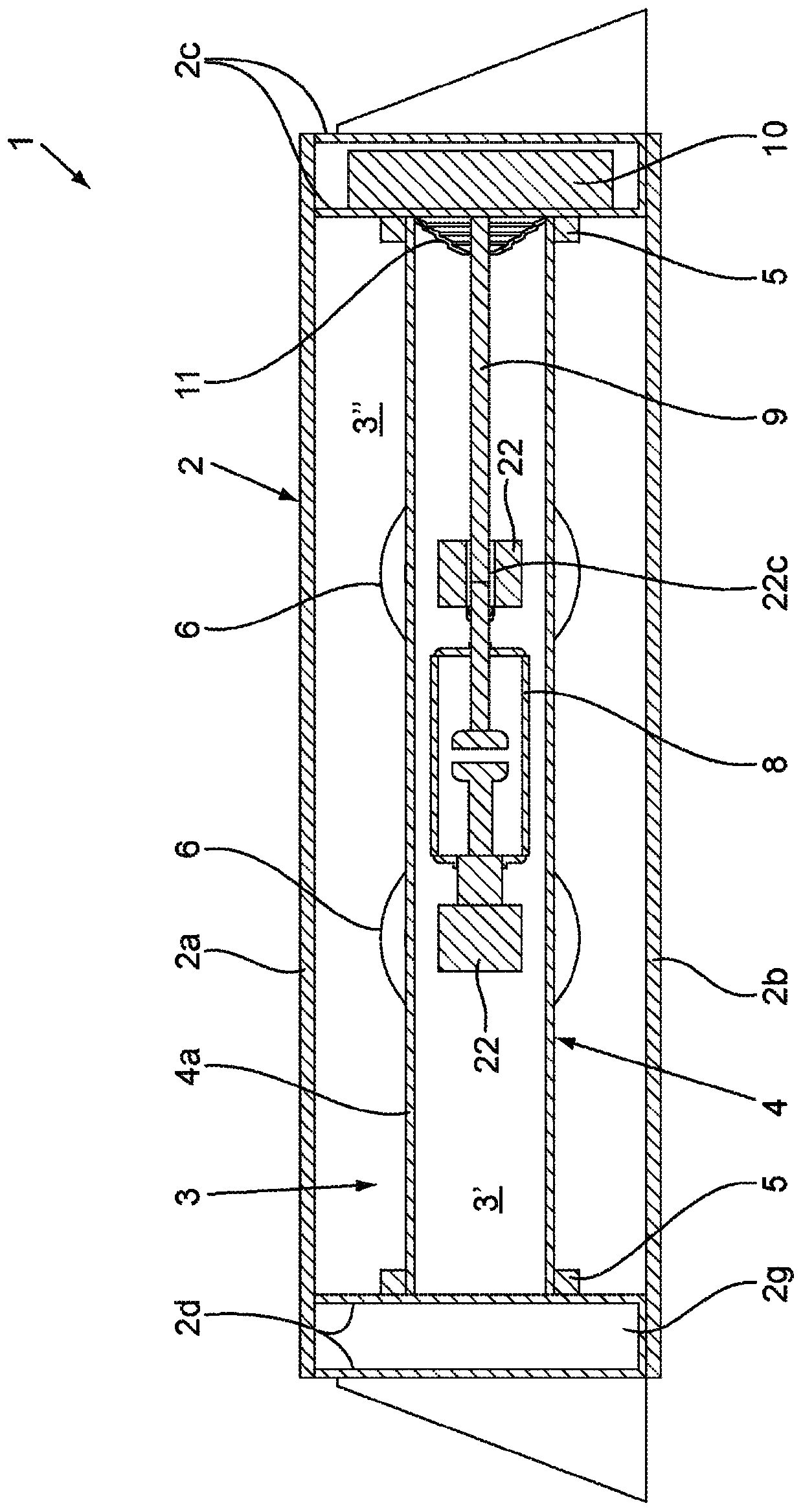
[0028] Figure 1 to Figure 3 An electrical switching device 1 for high or medium voltage according to the invention is shown in . The electrical switching device 1 comprises a housing 2 made of an electrically conductive material, typically made of a metallic material (metal or alloy). In use, the conductive housing 2 is grounded so that there is no electric field on its outer surface. The conductive housing 2 has the general shape of a cuboid and has a top wall 2a , a bottom wall 2b and side walls 2c , 2d , 2e , 2f which together define a sealed inner space 3 . In said sealed inner space 3 is installed an electrical insulation structure 4 comprising a main pipe 4a and an auxiliary pipe 4b. The main pipe 4a and the auxiliary pipe 4b are rigid. The main pipe 4a extends from the side wall 2c to the opposite side wall 2d in the longitudinal direction of the conductive housing 2 . Each auxiliary pipe 4b extends perpendicularly to the longitudinal direction of the conductive ho...
PUM
 Abstract
Description
Claims
Application Information
 - R&D Engineer
- R&D Manager
- IP Professional
- Industry Leading Data Capabilities
- Powerful AI technology
- Patent DNA Extraction
Browse by: Latest US Patents, China's latest patents, Technical Efficacy Thesaurus, Application Domain, Technology Topic, Popular Technical Reports.
© 2024 PatSnap. All rights reserved.Legal|Privacy policy|Modern Slavery Act Transparency Statement|Sitemap|About US| Contact US: help@patsnap.com