Fire-fighting guardrail convenient to mount

A fire-fighting and convenient technology, applied in the direction of fences, display devices, instruments, etc., can solve the problems of single structure, not convenient installation, poor stability, etc., and achieve the effect of improving protection effect and good safety warning effect

Inactive Publication Date: 2020-09-01
陈永严
View PDF0 Cites 0 Cited by
  • Summary
  • Abstract
  • Description
  • Claims
  • Application Information

AI Technical Summary

Problems solved by technology

[0003] However, the existing fire barriers are not easy to install, have

Method used


Image

  • Fire-fighting guardrail convenient to mount
  • Fire-fighting guardrail convenient to mount
  • Fire-fighting guardrail convenient to mount

Examples


Embodiment 1

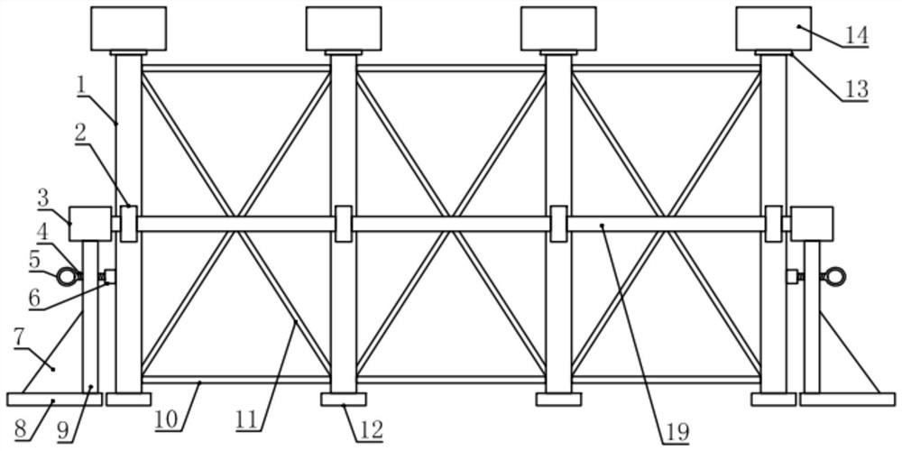
[0017] see figure 1 , in an embodiment of the present invention, a fire guardrail for convenient installation, including a plurality of support columns 1 arranged in sequence, the upper end of the support column 1 is detachably installed with a warning assembly, and the lower end of the support column 1 is installed and fixed with a second support Base 12, a plug-in fixing ring 2 is installed and fixed on the front and rear sides of the middle part of the supporting column 1, and a side fixing rod is respectively inserted in the plug-in fixing ring 2 on the front side and the rear side of several supporting columns 1 19. Two ends of the two side fixing rods 19 are detachably installed and fixed with an end support fixing assembly, and the end support fixing assembly is also used for detachable connection and fixing with the nearest support column 1, Two adjacent support columns 1 are also connected by elastic rope components.

[0018] In the embodiment of the present inventio...

Embodiment 2

[0020] see Figure 1-4 , the difference between this embodiment and embodiment 1 is:

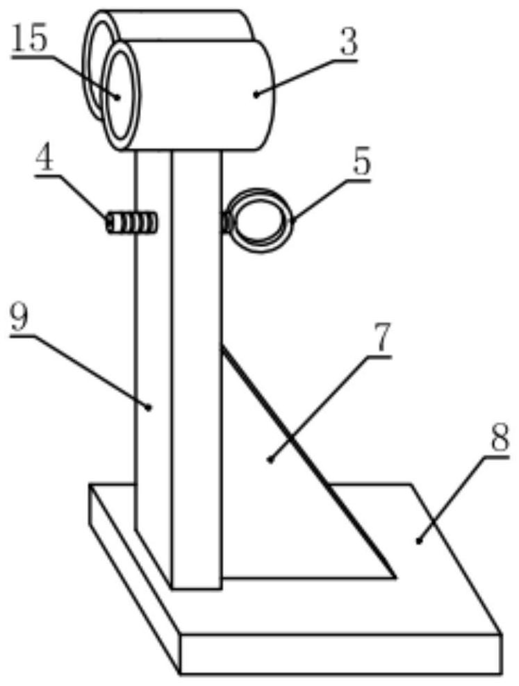
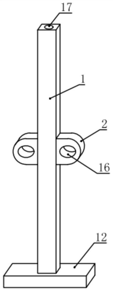
[0021] In this example, if image 3 As shown, the insertion fixing ring 2 is provided with an insertion hole 16 for the side fixing rod 19 to slide through; figure 2 As shown, the end support fixing assembly includes a fixed end seat 3, a threaded rod 4, a rotating ring 5, a threaded connection cylinder 6, a triangular reinforcement plate 7, a first support base 8 and a support vertical frame 9, and the fixed end The seat 3 includes two cylinders, and a fixing hole 15 that can be mated with a side fixing rod 19 is opened on the two cylinders, and a support vertical frame 9 is fixed on the lower side of the fixed end seat 3 to support The lower end of the vertical frame 9 is fixedly provided with a first supporting base 8, and a triangular reinforcing plate 7 is also installed between the first supporting base 8 and the supporting vertical frame 9, and the triangular reinforcing plate 7 is...


PUM


Abstract

The invention relates to the technical field of fire protection, in particular to a fire-fighting guardrail convenient to mount. The fire-fighting guardrail convenient to mount comprises a plurality of supporting stand columns which are arranged in sequence, wherein a warning assembly is detachably mounted at the upper end of each supporting stand column, a second supporting base is mounted and fixed at the lower end of each supporting stand column, an inserting fixing ring is mounted and fixed on each of the front side and back side of the middle part of each supporting stand column, a lateral fixing rod is inserted into the each of the inserting fixing rings on the front sides and back sides of the plurality of supporting stand columns, an end supporting and fixing assembly is detachablymounted and fixed at each of two ends of the two lateral fixing rods, the end supporting and fixing assemblies are further used for being detachably connected and fixed with the nearest supporting stand column, and every two adjacent supporting stand columns are connected through an elastic rope assembly. The fire-fighting guardrail is convenient to mount, novel in structure and excellent in stability and further has a warning effect.

Description

technical field [0001] The invention relates to the technical field of fire protection, in particular to a conveniently installed fire guardrail. Background technique [0002] Firefighting is the general term for preventing and solving the man-made, natural and accidental disasters that people encounter in their life, work and study. The fire protection system includes not only fire hydrants, fire trucks, fire extinguishers, etc., but also fire guardrails, which can play the role of protection and safety warning. [0003] However, the existing fire guardrails are not easy to install, have a single traditional structure, poor stability, and have no warning effect. Therefore, for the above present situation, it is urgent to develop a kind of convenient installation fire guardrail, to overcome the deficiencies in the current practical application. Contents of the invention [0004] The purpose of the embodiments of the present invention is to provide a convenient installati...

Claims


Application Information

Patent Timeline
IPC IPC(8): E04H17/14E04H17/20E04H17/22G09F7/18
CPCE04H17/1417E04H17/20E04H17/22G09F7/18G09F2007/1804G09F2007/1856G09F2007/1873
Inventor 陈永严
Owner 陈永严
Why Eureka
Try Eureka