Down filling device and filling method thereof
A technology of filling device and down, which is applied in the direction of dry gas arrangement, application, lighting and heating equipment, etc., which can solve the problems of low efficiency, waste of down, unfavorable uniform distribution of down, etc.
- Summary
- Abstract
- Description
- Claims
- Application Information
AI Technical Summary
Problems solved by technology
Method used
Image
Examples
Embodiment 1
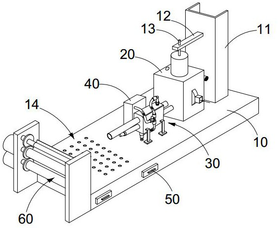
[0036] see Figure 1-9 As shown, the down filling device, including:
[0037] A frame 10, a drying box 20 is arranged on the frame 10, and a first installation pipe 24 and a second installation pipe 25 are provided on the sides of the drying box 20;
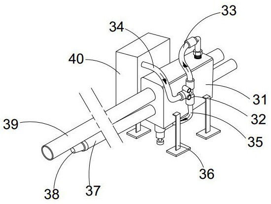
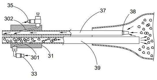
[0038] The down filling assembly 30, the down filling assembly 30 is arranged on the frame 10, the down filling assembly 30 includes a down filling base part 31, the fifth tube body 39 and the fourth tube body 37 are interspersed in the down filling base part 30, the fifth tube body The body 39 is assembled and connected with the first installation pipe 24, the fourth pipe body 37 is assembled and connected with the second installation pipe 25, and the other end of the fourth pipe body 37 is provided with a breather 38;
[0039] The filling base part 31 is respectively provided with the second auxiliary air passage 302 communicated with the fourth pipe body 37 and the first auxiliary air passage 301 communicated with the fifth p...
Embodiment 2
[0047] The down filling method using the down filling device has the following steps:
[0048] - Squeeze the down filling to remove part of the gas in the down filling;
[0049] -Put the nozzles of the fourth pipe body 37 and the fifth pipe body 39 into the down filling port of the down filling part, start the air pump 40, and use the air flow to promote the down and down in the drying tank 70 to enter the down filling part from the fifth pipe body 39 In the down filling process, the excess gas in the down filling part enters the fourth pipe body 38 through the breathable part 38, and the gas reflowed in the fourth pipe body 38 enters the drying tank 70 to improve the fluidity of the down in the tank.
[0050]In the present invention, the down is firstly dried to ensure that the down-filled down is dry and solves the hidden danger of down-filling that may exist in wet down. The gas flows along the first auxiliary air channel 301 in the down-filled base part 31 and flows towar...
Embodiment 3
[0053] The present embodiment is further optimized on the basis of embodiment 1 as follows: see attached figure 1 , 10 , 11, the frame 10 is provided with a cavity, and a filling area 14 is formed between the upper surface of the cavity and the surface of the frame 10, and the surface of the frame 10 in the filling area 14 is provided with a continuous suction hole 15, and the filling area The upper surface of the cavity below 14 is provided with corrugated deflectors 16 in a row, and fans 52 are arranged in a row in the cavity.
[0054] The side wall of the frame 10 is provided with a through groove communicating with the cavity. The first pulling member 52 is inserted into the through groove and can be pulled inside and outside the relatively through groove. The part of the pulling member 52 located in the cavity is disposed on the side of the fan.
PUM
 Abstract
Description
Claims
Application Information
 - R&D
- Intellectual Property
- Life Sciences
- Materials
- Tech Scout
- Unparalleled Data Quality
- Higher Quality Content
- 60% Fewer Hallucinations
Browse by: Latest US Patents, China's latest patents, Technical Efficacy Thesaurus, Application Domain, Technology Topic, Popular Technical Reports.
© 2025 PatSnap. All rights reserved.Legal|Privacy policy|Modern Slavery Act Transparency Statement|Sitemap|About US| Contact US: help@patsnap.com


