Supercharge Your Innovation With Domain-Expert AI Agents!

A high-strength connector termination structure

A connector, high-strength technology, applied in the direction of connection, conductive connection, clamping/spring connection, etc., can solve the problems of increasing the procurement cost of crimping tools, being unsuitable for high-current connectors, reducing the elastic force of shrapnel, and achieving structural Simple, low cost, and the effect of ensuring connection reliability

Active Publication Date: 2021-04-30
TAIZHOU HANGYU ELECTRICAL DEVICE
View PDF4 Cites 0 Cited by
  • Summary
  • Abstract
  • Description
  • Claims
  • Application Information

AI Technical Summary

Problems solved by technology

The screw locking type is relatively convenient. Since the screw and the wire are in point contact, it is not suitable for the use of high-current connectors. In addition, the product is required to have enough screw locking space
However, when crimping products are used in high-heat places, there is no risk of soldering and short circuit caused by solder melting, and crimping products can be wired on site. Most of the crimping products in the prior art use shrapnel crimping. Yes, the shrapnel pressure is restricted by the elastic force of the shrapnel. When the wire heats up, it will directly reduce the elastic force of the shrapnel, resulting in a decrease in connection reliability. In addition, for high-current connectors, special hydraulic pressure is required when the shrapnel is crimped. Tools, which are inconvenient to carry and increase the purchase cost of crimping tools

Method used


Image

  • A high-strength connector termination structure
  • A high-strength connector termination structure
  • A high-strength connector termination structure

Examples


Embodiment Construction

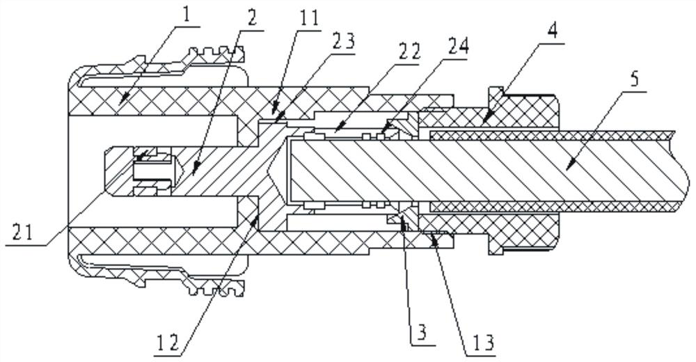
[0021] refer to figure 1 , The present invention includes a housing 1, a contact piece 2, a compression ring 3 and a pressure cap 4 at the end.

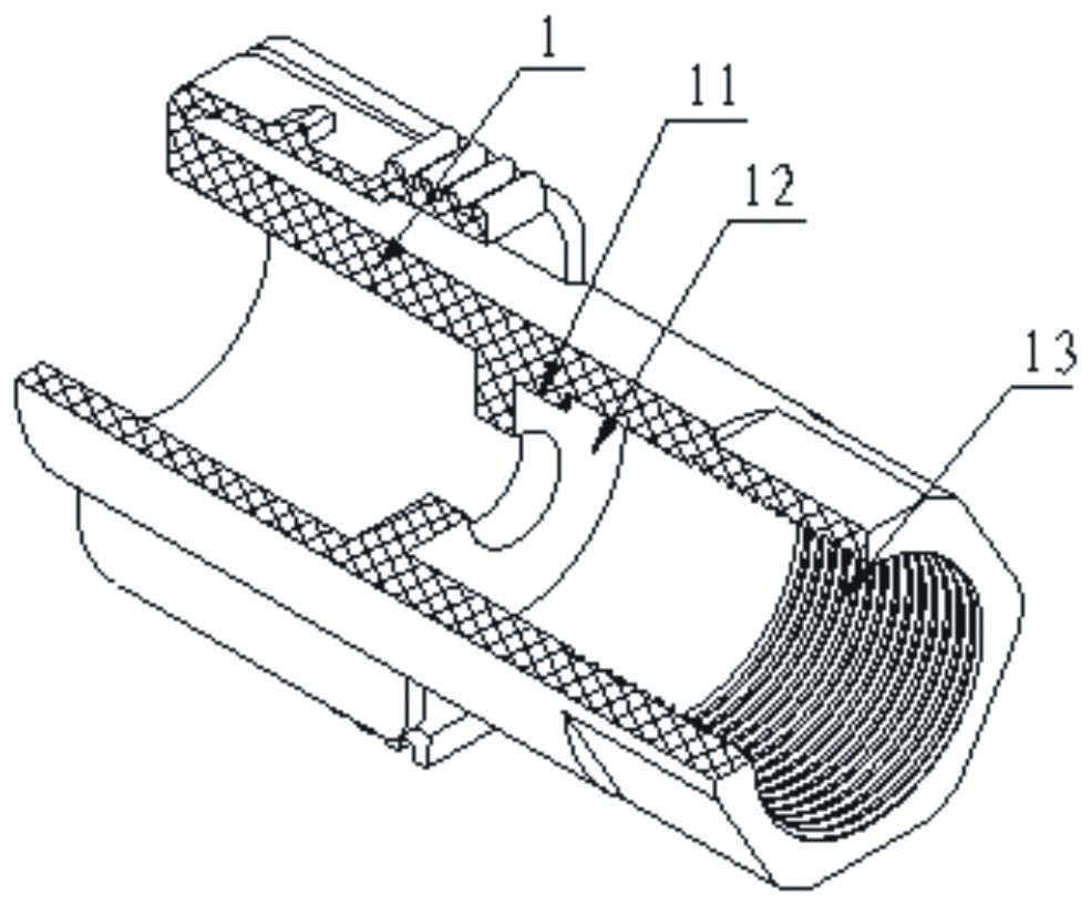
[0022] refer to figure 1 , figure 2 , the shell 1 is a cylindrical member, a stepped hole 12 and an internal thread 13 are provided in the cylinder, and a positioning convex key 11 is provided on the inner wall of the cylinder.

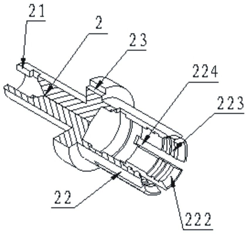
[0023] refer to figure 1 , image 3 , the contact piece 2 is a shaft-shaped member with a contact 21 at one end, an elastic cylinder wall 22 at the other end, and a limit boss in the middle. A keyway 23 is provided on the limit boss, and the circumference of the elastic cylinder wall 22 A plurality of elastic arms 222 are provided, and engaging teeth 223 are provided inside the elastic arms 222 .

[0024] refer to figure 1 , Figure 4 , the pressing ring 3 is a ring member, and the inner hole of the ring member is provided with a bell mouth 31 .

[0025] refer to figure 1 , Figure 5 , the tail-en...


PUM


Abstract

The invention discloses a high-strength connector termination structure, which includes a shell, a contact piece, a compression ring and a tail-end pressure cap; the invention adopts a structure in which the contact piece, the compression ring and the tail-end pressure cap are arranged in the shell , one end of the contact piece is provided with an elastic cylinder wall, several elastic arms are arranged around the circumference of the elastic cylinder wall, and teeth are provided on the inner side of the elastic arms; the core wire of the cable is inserted into the elastic cylinder wall, and passed through the tail end The pressure cap pushes the compression ring, and the bell mouth of the compression ring forces the elastic arm to draw in, and the core wire is fixedly connected with the contact piece through the occlusal teeth on the elastic arm. The crimping method of the present invention does not reduce the bite force of the elastic arm due to heating of the wire, ensures the connection reliability of the cable, and has the advantages of simple structure, convenient connection, safe and reliable connection and low cost.

Description

technical field [0001] The invention relates to the technical field of electrical connectors, in particular to a high-strength connector termination structure. Background technique [0002] Traditional connector termination structures mainly include welding type, screw locking type and crimping type. The soldering type is mainly used in occasions where the current is small and the heat generation is low, otherwise the overheating effect will easily lead to melting of the solder, which may easily cause false welding and short circuit. The screw locking type is relatively convenient. Since the screw and the wire are in a point contact state, it is not suitable for the use of high-current connectors. In addition, the product is required to have enough screw locking space. However, when crimping products are used in high-heat places, there is no risk of soldering and short circuit caused by solder melting, and crimping products can be wired on site. Most of the crimping product...

Claims


Application Information

Patent Timeline
Patent Type & Authority Patents(China)
IPC IPC(8): H01R11/11H01R4/48
CPCH01R4/489H01R11/11
Inventor 顾晶丁晟叶留芳卞如民
Owner TAIZHOU HANGYU ELECTRICAL DEVICE
Features
  • R&D
  • Intellectual Property
  • Life Sciences
  • Materials
  • Tech Scout
  • Unparalleled Data Quality
  • Higher Quality Content
  • 60% Fewer Hallucinations
Learn More