Disinfection cabinet handle
A technology for disinfection cabinets and handles, which is applied in the direction of disinfection, wing fan handles, wing fan ball handles, etc. It can solve the problems of bacteria breeding, complex structure, slippery and greasy kitchen floor, etc.
- Summary
- Abstract
- Description
- Claims
- Application Information
AI Technical Summary
Problems solved by technology
Method used
Image

Examples
Embodiment 1
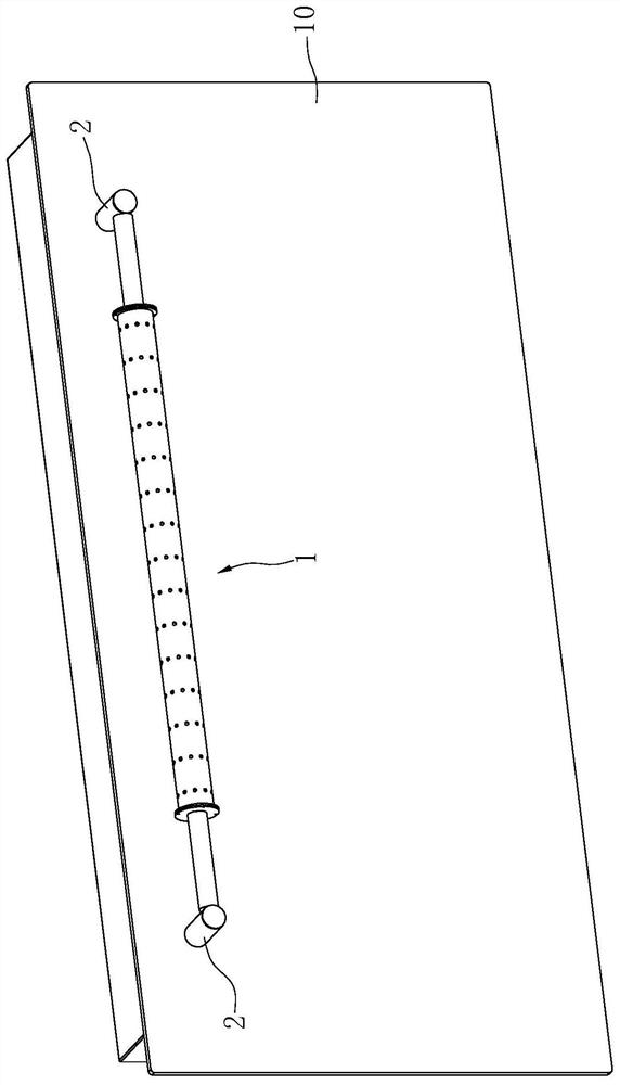
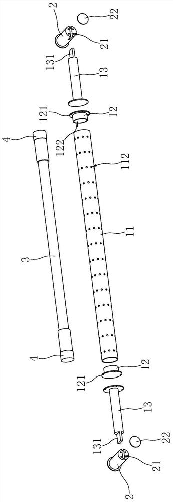
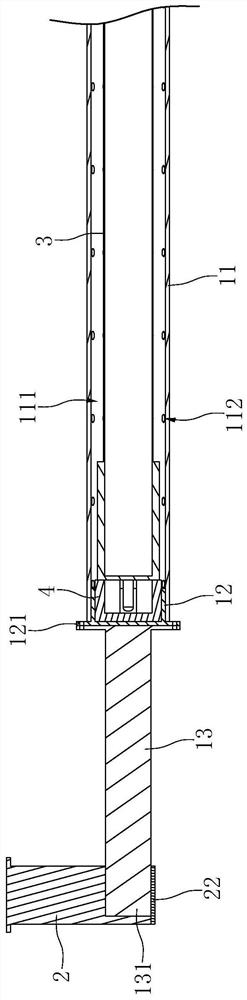
[0043] Such as Figure 1 to Figure 3 Shown is the first preferred embodiment of the disinfection cabinet handle of the present invention. The disinfection cabinet handle includes a handle 1 , two mounting seats 2 respectively connected to two ends of the handle 1 , a disinfection unit 3 installed in the handle 1 and two lamp sockets 4 .
[0044] Wherein, the handle 1 includes a protective cylinder 11 , a plug 12 and a connecting rod 13 . Specifically, an accommodating cavity 111 is formed inside the protective tube 11, and the two ends of the protective tube 11 have openings, and at least two groups of through holes for the disinfection light to pass are opened on the peripheral wall of the protective tube 11, and each through hole group Arranged at intervals along the circumference of the protective tube 11, each group of through holes includes at least two through holes 112 arranged at intervals along the length direction of the protective tube 11, the distance between two ...
Embodiment 2
[0049] Such as Figure 4 to Figure 6 Shown is the second preferred embodiment of the disinfection cabinet handle of the present invention. The difference with Example 1 is:
[0050] In this embodiment, the outer circumference of the protective tube 11 is provided with two shading sleeves 5, the length of the shading sleeves 5 is shorter than that of the protective tube 11, and the shading sleeves 5 can move relative to the handle 1 along the length direction of the handle 1, and are used for communication. The hole 112 is either opened or closed. Specifically, the length of the shading cover 5 is 1 / 4 of the length of the protective tube 11, and the through hole 112 is arranged in the middle of the protective tube 11, such as Figure 5As shown, in the state where the ends of the two light-shielding sleeves 5 abut against the above-mentioned limit protrusion 121, all the through holes 112 are fully opened; as Figure 6 As shown, in the state where the ends of the two light-sh...
Embodiment 3
[0053] Such as Figure 7 to Figure 9 Shown is the second preferred embodiment of the disinfection cabinet handle of the present invention. The difference with embodiment 2 is:
[0054] In this embodiment, a light-transmitting hole 51' corresponding to the through hole 112 is opened on the light-shielding sleeve 5', the length of the light-shielding sleeve 5 is the same as that of the protective tube 11, and the end surface of the light-shielding sleeve 5' is offset against the limit protrusion 121. And the shading cover 5' can rotate around the axis of the handle 1 relative to the handle 1 to open or close the through hole 112: when the light-transmitting hole 51' of the shading cover 5' communicates with the through hole 112, the through hole 112 Open; when the light-shielding sleeve 5' covers the through hole 112, the through hole 112 is closed.
[0055] In order to limit the limit position when the shading cover 5' rotates, the surface of the limit protrusion 121 is provi...
PUM
 Abstract
Description
Claims
Application Information
 - R&D
- Intellectual Property
- Life Sciences
- Materials
- Tech Scout
- Unparalleled Data Quality
- Higher Quality Content
- 60% Fewer Hallucinations
Browse by: Latest US Patents, China's latest patents, Technical Efficacy Thesaurus, Application Domain, Technology Topic, Popular Technical Reports.
© 2025 PatSnap. All rights reserved.Legal|Privacy policy|Modern Slavery Act Transparency Statement|Sitemap|About US| Contact US: help@patsnap.com