
Sterilization device based on microsecond high-voltage pulse power supply

A technology of sterilization and disinfection device and high-voltage pulse power supply, which is applied in the field of high-voltage pulse power supply, can solve the problems of high cost, limited application range, switch damage, etc., and achieve the effect of high output voltage, high reliability and simple structure

Pending Publication Date: 2020-07-03
北京钵汇五方科技有限公司
View PDF7 Cites 2 Cited by
  • Summary
  • Abstract
  • Description
  • Claims
  • Application Information

AI Technical Summary

Problems solved by technology

[0002] In related technologies, the circuit topology of high-voltage pulse power supply for sterilization and disinfection is based on high-voltage switch pulse power supply. One is to use a high-voltage switch alone. This solution has particularly high requirements for high-voltage switch technology, so the cost is also particularly high. , the technology is difficult, and the switching voltage level is not very high, so the scope of application is limited, and it is mostly used in the laboratory; the other is to use the semiconductor switch in series as a high-voltage switch. Due to the production process, the switching characteristics of these devices may have relatively large differences, and it is prone to switch damage, which affects the reliable operation of the power supply.

Method used


Image

  • Sterilization device based on microsecond high-voltage pulse power supply
  • Sterilization device based on microsecond high-voltage pulse power supply

Examples


specific Embodiment

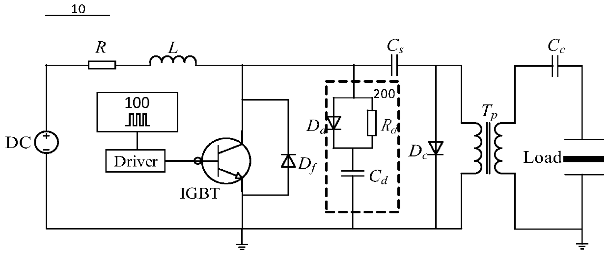
[0032]Further, in one embodiment of the present invention, microsecond high-voltage pulse power supply drives DBD for sterilization and disinfection. The pulse voltage requirement is about 30-40kV, the pulse width is at the μs level, and the repetition frequency is 1kHz. The small-scale sterilization and disinfection device The power is about several hundred watts, specifically: the pulse peak voltage is up to 50kV, the polarity is adjustable, the pulse width is 3μs to 20μs, the repetition frequency is adjustable within 1kHz, and the maximum power is 1kW. Specific examples are as follows:

[0033] High-voltage direct-current power supply DC: The selected parameters are a direct-current power supply with a rated voltage of 1000V and a rated power of 1kW.

[0034] IGBT switch: Since the price of the IGBT switch increases rapidly with the increase of the voltage level, the voltage level of the selected IGBT switch device is 1200V, which is relatively cheap and has high stability;...


PUM

PropertyMeasurementUnit
Pulse widthaaaaaaaaaa
Capacitanceaaaaaaaaaa

Abstract

The invention discloses a sterilization device based on a microsecond high-voltage pulse power supply. The device comprises a high-voltage direct current power supply, a current-limiting resistor, a current-limiting inductor, an insulated gate bipolar transistor (IGBT), a driver, a signal generator, a buffer absorption circuit, a first diode, a pulse transformer and an energy storage capacitor; one end of the current-limiting resistor is connected with the positive electrode of the high-voltage direct current power supply, and the other end of the current-limiting resistor is connected with one end of the current-limiting inductor; an IGBT collector is connected with the other end of the energy storage capacitor and one end of the energy storage capacitor; an IGBT emitter is connected withthe negative electrode of the high-voltage direct current power supply and is grounded; an IGBT gate is connected with a first end of the driver; a second end of the driver is connected with the signal generator; the buffer absorption circuit, the IGBT, the first diode and the pulse transformer are connected in parallel; the negative pole of the first diode is grounded; and the positive pole of the first diode is connected with the other end of the energy storage capacitor. After low-voltage pulse is generated, high-pulse voltage output is realized by combination of the pulse transformer forsterilization and disinfection. The device adopts the low-cost microsecond high-voltage pulse power supply to realize sterilization and disinfection.

Description

technical field [0001] The invention relates to the technical field of high-voltage pulse power supply, in particular to a sterilization and disinfection device based on microsecond high-voltage pulse power supply. Background technique [0002] In related technologies, the circuit topology of high-voltage pulse power supply for sterilization and disinfection is based on high-voltage switch pulse power supply. One is to use a high-voltage switch alone. This solution has particularly high requirements for high-voltage switch technology, so the cost is also particularly high. , the technology is difficult, and the switch voltage level is not very high, so the application range is limited, and it is mostly used in the laboratory; the other is a high-voltage switch in which semiconductor switches are connected in series. Due to the production process, the switching characteristics of these devices may have relatively large differences, and it is easy to cause switch damage, which...

Claims


Application Information

Patent Timeline
IPC IPC(8): A61L2/03A61L2/26A61L2/24
CPCA61L2/03A61L2/26A61L2/24
Inventor 杨坤罗海云邹晓兵王新新
Owner 北京钵汇五方科技有限公司
Learn More