Medical suspension injection bottle and medical bottle suspension assembly
A technology of injection bottle and telescopic assembly, applied in the field of medical syringes, can solve the problems of contact infection, injury, accidental contact with the skin of patients with infusion needles, etc., and achieve the effect of good support and low impact.
- Summary
- Abstract
- Description
- Claims
- Application Information
AI Technical Summary
Problems solved by technology
Method used
Image

Examples
Embodiment 1
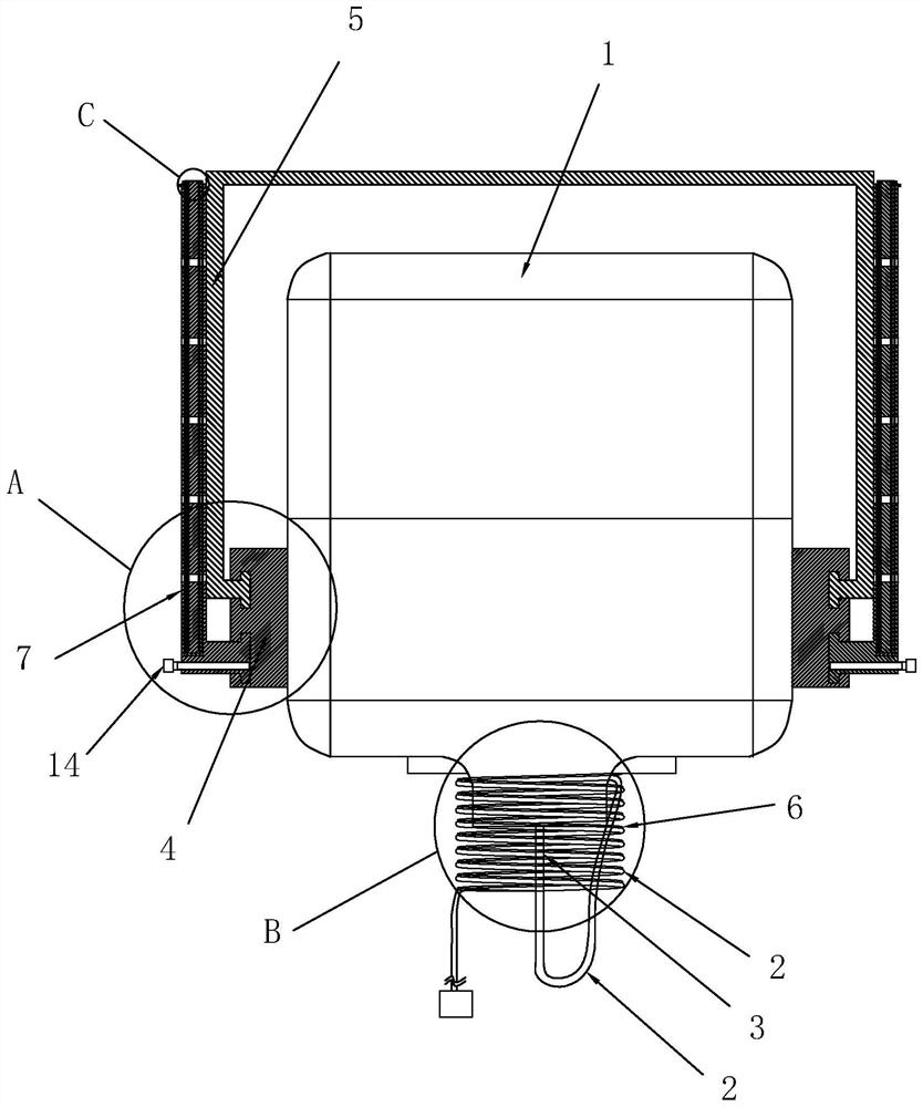
[0035] Embodiment one: see figure 1 as well as Figure 5 .
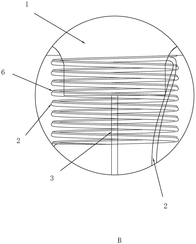
[0036] A medical hanging injection bottle, comprising a drop bottle 1, an infusion tube 2, and a needle 3 connected to the end of the infusion tube 2.
[0037] by figure 1 For the orientation reference direction, the bottle mouth of the drip bottle 1 is set downward, and a mounting frame 4 is fixedly arranged on the outside of the drip bottle 1, and a suspension rod 5 is arranged on the mounting frame 4. The suspension rods 5 are provided with two, two The suspenders 5 are symmetrically arranged on both sides of the drip bottle 1. One end of the suspenders 5 is hinged to the mounting frame 4, and the other ends of the two suspenders 5 are connected by a connecting rod. The entire suspenders 5 and the connecting rods are C-shaped. structure, the suspender 5 is used to hang the drip bottle 1 on a position at a specified height.
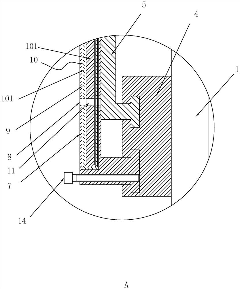
[0038] Mounting frame 4 is also rotatably connected with fixed rod 7. In this embodime...
Embodiment 2
[0048] Embodiment two: see Figure 5 as well as Figure 6 .
[0049] A medical hanging bottle assembly, including a mounting bar 15 and a medical hanging injection bottle as in Embodiment 1, the mounting bar 15 is provided with a hook 17 for hanging the suspender 5, and the mounting bar 15 is made of iron As a result, the end of the telescopic assembly 10 is provided with a magnetic attraction block 16 , and the end of the telescopic assembly 10 can be in contact with the installation crossbar 15 and generate a magnetic attraction effect with the installation crossbar 15 .
[0050] During specific use:
[0051] Hang the suspension rod 5 on the hook 17, rotate the fixed rod 7 close to the position of the suspension rod 5, a magnetic attraction effect is generated between the fixed rod 7 and the suspension rod 5, and by moving the telescopic assembly 10, the magnetic block on the telescopic assembly 10 16 can produce magnetic attraction to installation crossbar 15. In additi...
PUM
 Abstract
Description
Claims
Application Information
 - Generate Ideas
- Intellectual Property
- Life Sciences
- Materials
- Tech Scout
- Unparalleled Data Quality
- Higher Quality Content
- 60% Fewer Hallucinations
Browse by: Latest US Patents, China's latest patents, Technical Efficacy Thesaurus, Application Domain, Technology Topic, Popular Technical Reports.
© 2025 PatSnap. All rights reserved.Legal|Privacy policy|Modern Slavery Act Transparency Statement|Sitemap|About US| Contact US: help@patsnap.com