
Steel truss girder bridge girder transporting flatcar

A technology for transporting beams and flat cars, which is applied to bridges, goods transport vehicles, vehicles used for freight transportation, etc., can solve problems such as affecting the center of gravity of vehicles, danger, and shortening the service life of bridges, so as to reduce the possibility of shaking and the degree of shaking. , Improve the service life and use safety, improve the effect of safety

Active Publication Date: 2020-09-04
HUNAN CITY UNIV
View PDF10 Cites 1 Cited by
  • Summary
  • Abstract
  • Description
  • Claims
  • Application Information

AI Technical Summary

Problems solved by technology

[0003] Aiming at the deficiencies of the prior art, the present invention provides a steel truss bridge beam transport flat car, which solves the problem that most of the existing beam transport flat cars use steel cables or ropes for binding after carrying structural parts, and steel cables and The rope has a certain degree of ductility, so it is easy to cause the structural parts to shake due to the complex road conditions at the construction site during transportation, and its huge weight can easily affect the driving center of gravity of the vehicle, causing a great safety hazard; at the same time, due to the binding effect When the structural joints are shaken due to poor performance, different parts of the structural joints are susceptible to pulling forces in different directions and their own shearing forces, which are likely to cause hidden damage to the structural joints themselves, which not only reduces the service life of the bridge, but also has a large Dangerous; and there is no good protective measures between the cab and the structural joints. If the vehicle brakes suddenly due to an emergency during transportation, the structural joints are easy to move forward on the vehicle body, posing a life-threatening problem to the driver.

Method used


Image

  • Steel truss girder bridge girder transporting flatcar
  • Steel truss girder bridge girder transporting flatcar
  • Steel truss girder bridge girder transporting flatcar

Examples


Embodiment Construction

[0025] The following will clearly and completely describe the technical solutions in the embodiments of the present invention with reference to the accompanying drawings in the embodiments of the present invention. Obviously, the described embodiments are only some, not all, embodiments of the present invention. Based on the embodiments of the present invention, all other embodiments obtained by persons of ordinary skill in the art without making creative efforts belong to the protection scope of the present invention.

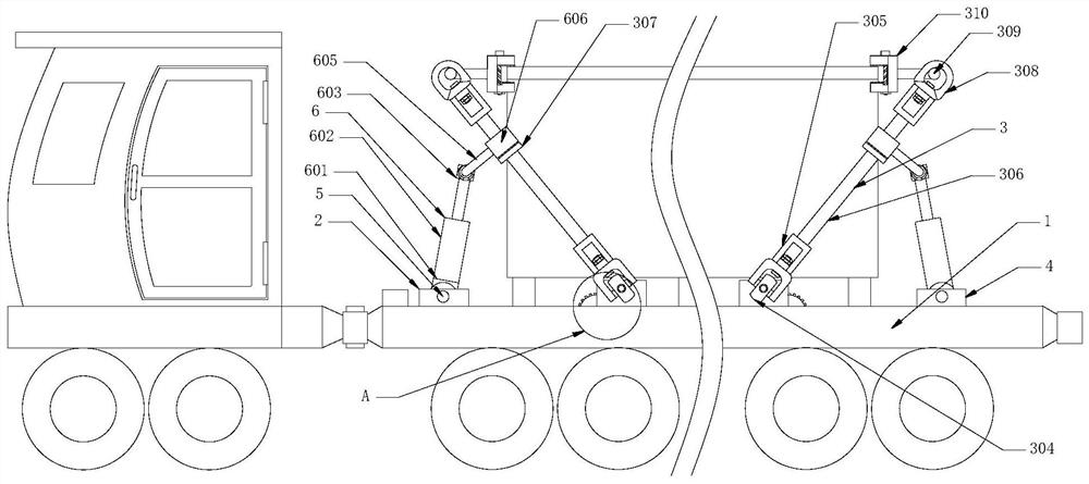
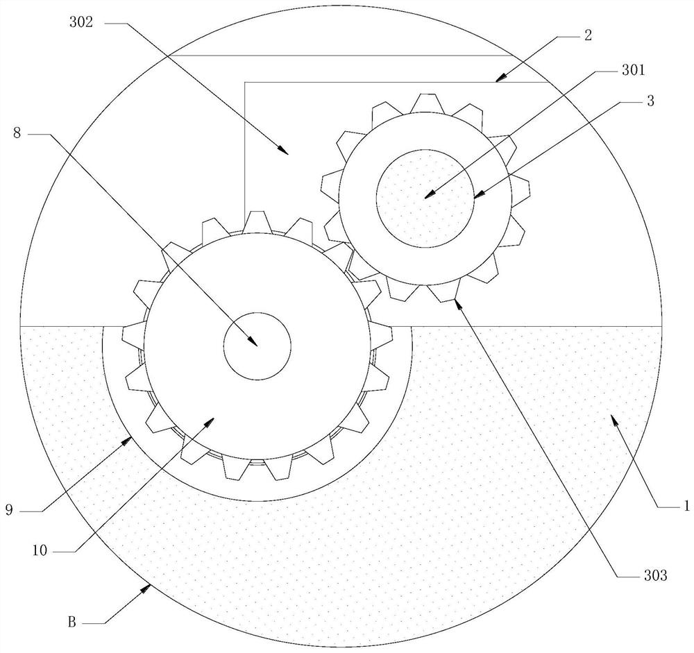
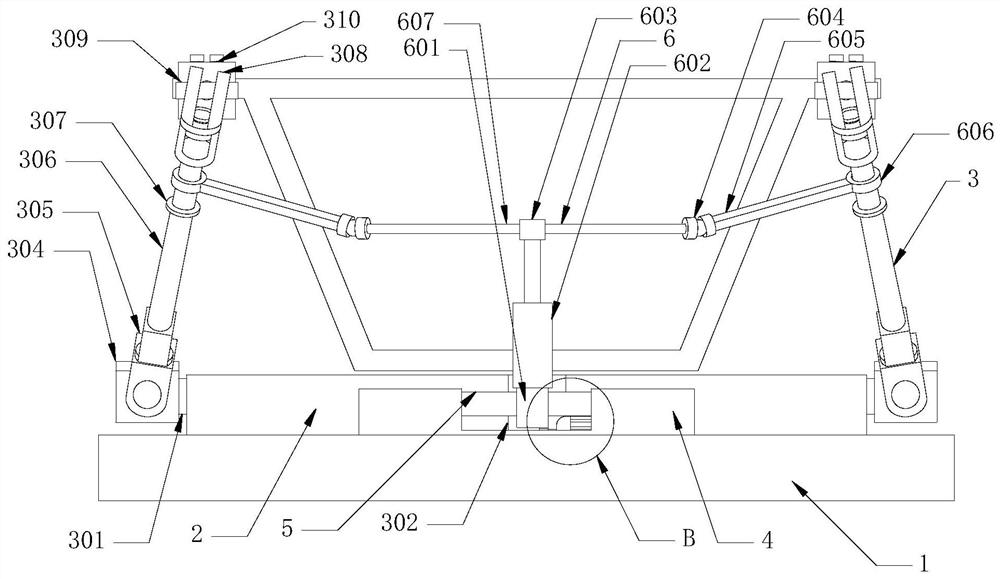
[0026] see Figure 1-4 , a steel truss girder bridge beam transport flat car, comprising a body 1, the left and right sides of the top surface of the body 1 are fixedly connected with a base 2, the surface of the base 2 is rotatably connected with a fastening mechanism 3, and the fastening mechanism 3 is used for The connecting member is connected with the vehicle body 1, the left and right sides of the top surface of the vehicle body 1 are fixedly connected w...


PUM


Abstract

The invention discloses a steel truss girder bridge girder transporting flatcar, which comprises a flatcar body, wherein bases are fixedly connected to the left side and the right side of the top faceof the flatcar body. The invention relates to the technical field of bridge engineering. According to the steel truss girder bridge girder transporting flatcar, an adjusting mechanism is matched witha fastening mechanism to lock a structural connecting piece and the flatcar body, the fixing stability of the structural connecting piece and the flatcar body is greatly improved, the driving gravitycenter of the vehicle is prevented from being influenced by shaking and impacting the vehicle due to external factors, the safety in the transportation process is effectively improved, the shaking possibility and the shaking degree of the structural connecting piece on the flatcar body are greatly reduced, the hidden injury caused by multi-directional pulling force and self shearing force when the structural connecting piece shakes is effectively avoided, the service life of the bridge is greatly prolonged, and the use safety of the bridge is greatly improved. Meanwhile, the adjusting mechanism can form a frame structure between a cab and the structural connecting piece, the forward-moving structural connecting piece can be blocked and buffered during emergency braking, and the safety ofa driver is effectively improved.

Description

technical field [0001] The invention relates to the technical field of bridge engineering, in particular to a steel truss bridge girder transport flat car. Background technique [0002] The steel truss girder bridge is a structural form in which the solid-web steel plate girder bridge is hollowed according to certain rules. The structure as a whole is a beam-bearing mode, that is, a structure that mainly bears bending moment and shear force. , bearings and bridge piers (abutments), because high-altitude construction is dangerous and difficult to construct, so in the process of bridge construction, most of the bridges will not be assembled at high altitude along the bridge body. Usually, after the construction personnel assemble a certain section of the bridge on the ground, the section is transported to the construction site by a beam-carrying flat car and lifted to a high altitude for segmental assembly. Most of the beam transport flat cars are bound with steel cables or r...

Claims


Application Information

Patent Timeline
Patent Type & Authority Applications(China)
IPC IPC(8): B60P3/00B60P7/10E01D2/04
CPCB60P3/00B60P7/10E01D2/04
Inventor 郑良飞刘兰
Owner HUNAN CITY UNIV
Learn More