Bumper with shock absorption function for new energy automobile

A new energy vehicle, bumper technology, applied in bumpers, vehicle parts, vehicle safety arrangements, etc., can solve the problem of low protection performance, and achieve the effect of strong practical performance, improved protection performance, and good anti-collision performance.

Active Publication Date: 2020-09-04
永康市能泽科技有限公司
View PDF9 Cites 2 Cited by
  • Summary
  • Abstract
  • Description
  • Claims
  • Application Information

AI Technical Summary

Problems solved by technology

[0003] The purpose of the present invention is to provide a bumper for new energy vehicles with a shock absorbing function, to solve the problem that most of the bumpers in the prior art proposed in the above background technology protect the car through the outer shell, and the protection performance is too low The problem

Method used


Image

  • Bumper with shock absorption function for new energy automobile
  • Bumper with shock absorption function for new energy automobile
  • Bumper with shock absorption function for new energy automobile

Examples


Embodiment 1

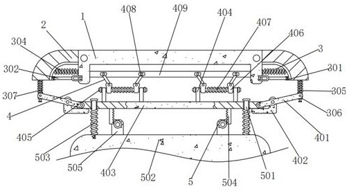
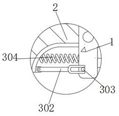
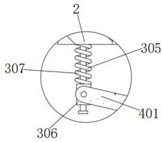
[0035]A bumper for a new energy vehicle with a shock absorbing function, comprising a bumper shell 1 and an arc plate 2, the left and right sides of the bumper shell 1 are movably connected with the arc plate 2 through pin shafts, and the arc plate 2 The bumper shell 2 can be rotated through the pin shaft, and the inner side of the left and right arc plates 2 is equipped with an elastic device 3, and the elastic device 3 includes a square block 301, an arc rod 302, a circular block 303, and a first spring 304 , the first vertical rod 305, the sleeve 306 and the second spring 307, the outsides of the left and right square blocks 301 are fixedly connected with the inner side of the arc plate 2, and the front ends of the left and right square blocks 301 are movably connected with arc rods 302 through pin shafts , the arc rod 302 can be rotated at the square block 301 through the pin shaft, and the inner side of the left and right arc rods 302 is equipped with a circular block 303,...

Embodiment 2

[0038] Embodiment 2: When the operator needs to use a bumper for a new energy vehicle with shock absorption function, the operator first adjusts the position of the arc plate 2 to be parallel to the bumper shell 1, and when the bumper shell 1 is hit , the bumper housing 1 drives the second horizontal plate 409 to move, the second horizontal plate 409 drives the second connecting rod 408 to move, the second connecting rod 408 drives the bump 406 to move on the cross bar 405, and the bump 406 Squeeze the third spring 407 to achieve shock absorption through the elastic properties of the third spring 407. At the same time, the bump 406 drives the first vertical plate 404 to move through the cross bar 405, and the first vertical plate 404 drives the first horizontal plate. 403 moves, the first horizontal plate 403 drives the tooth plate 504 to move, the tooth plate 504 drives the half gear 506 to rotate, and the first horizontal plate 403 squeezes the fourth spring 503 at the same t...


PUM


Abstract

The present invention discloses a bumper with a damping function for a new energy automobile. The bumper comprises a bumper shell and arc-shaped plates, the left side and the right side of the bumpershell are movably connected with the arc-shaped plates through pin shafts, and elastic devices are installed on the inner sides of the left arc-shaped plate and the right arc-shaped plate. According to the bumper with the damping function for the new energy automobile, through mutual cooperation of a first vertical plate, a third spring, a second connecting rod, a second transverse plate and otherstructures, when the device is impacted, the damping effect can be achieved; through mutual cooperation of the arc-shaped plates, afirst spring, a second spring, a first connecting rod, an L-shaped plate and a first transverse plate, when the arc-shaped platesareimpacted in other directions, the impact force can be reduced through the elastic performance of the first spring and the second spring;and through mutual cooperation of structures such as afirst transverse plate, asecond vertical plate, a fourth spring, a toothed plate, a gear and the second vertical plate, the impact force borne bythe first transverse plate can be further weakened, and the practical performance is higher.

Description

technical field [0001] The invention relates to the technical field of new energy vehicles, in particular to a bumper for new energy vehicles with a shock absorbing function. Background technique [0002] New energy vehicles refer to the use of unconventional vehicle fuels as the power source, comprehensive vehicle power control and advanced technology in driving, and the formation of vehicles with advanced technical principles, new technologies and new structures, which are required in new energy vehicles The bumper is installed. When a collision occurs, the bumper is an important part and an indispensable part of the structure of a modern electric vehicle as a safety protection device. It can effectively reduce the degree of casualties and the degree of damage to the car, while in the prior art Most of the bumpers protect the car through the shell, and the protection performance is too low. At the same time, it cannot achieve the shock absorption of the car in the event of...

Claims


Application Information

Patent Timeline
Patent Type & Authority Applications(China)
IPC IPC(8): B60R19/18
CPCB60R19/18B60R2019/1893
Inventor 张伟彬周菊燕
Owner 永康市能泽科技有限公司
Why Eureka
Try Eureka