Steel needle feeding structure

A steel needle and material feeding technology, which is applied to conveyors, manipulators, chucks, etc., can solve problems such as high cost, low feeding efficiency, and complex structure

Pending Publication Date: 2020-09-04
ZHEJIANG UNIV KUNSHAN INNOVATION INST
View PDF0 Cites 1 Cited by
  • Summary
  • Abstract
  • Description
  • Claims
  • Application Information

AI Technical Summary

Problems solved by technology

[0002] When feeding the existing steel needle assembly, it is necessary to move the structure to pull out the steel needle once, then the steel needle is clamped by the manipulator, and then the steel needle is transported to the corresponding carrier through the linear conveying mechanism. The structure is relatively complex, the cost is high, and the feeding efficiency is not high

Method used


Image

  • Steel needle feeding structure

Examples


Embodiment Construction

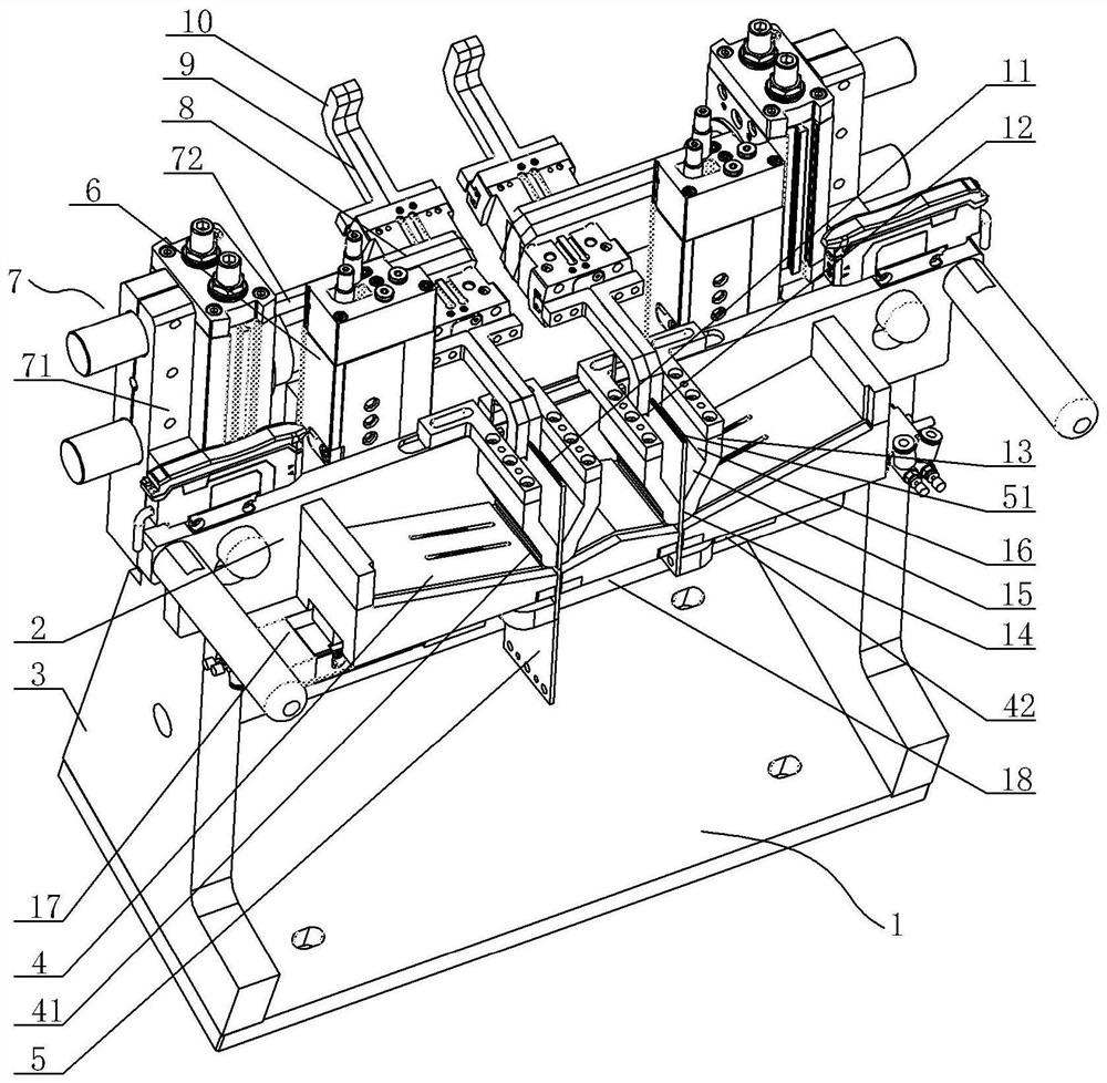
[0015] Steel needle feeding structure, see figure 1 : It includes a base 1, a connecting plate 2 is arranged between the upper surface of the base 1, the two ends of the connecting plate 2 are respectively connected to the side plates 3 on both sides of the base 1, and a connecting plate 2 is respectively arranged on both sides of the front end of the upper surface of the base 1 The steel needle material box 4, the output port 41 of the steel needle material box 4 is provided with a jacking plate 5, the bottom of the jacking plate 5 is connected to the lower output end of the corresponding jacking cylinder 6 through a connecting device, and the jacking cylinder 6 is fixed At the corresponding positions on the rear surface of the connecting plate 2, the cylinder bases 71 of the rotary cylinder 7 are respectively fixed on both sides of the rear surface of the connecting plate 2, and the end of the rotary output shaft 72 of the rotary cylinder 7 is sleeved with a clamping part fix...


PUM


Abstract

The invention provides a steel needle feeding structure. Steel needles are fed rapidly and conveniently, the whole structure is simple, the manufacturing cost is low, and the feeding efficiency is high. The steel needle feeding structure comprises a base. A connecting plate is arranged between the upper surface of the base, the two ends of the connecting plate are connected with side plates on thetwo sides of the base correspondingly, steel needle material boxes are arranged on the two sides of the front end of the upper surface of the base correspondingly, ejector plates are arranged at thepositions of output ports of the steel needle material boxes, the bottoms of the ejector plates are connected with the lower output ends of corresponding ejector air cylinders through connecting devices, the ejecting air cylinders are fixedly arranged at the corresponding positions of the rear surface of the connecting plate, cylinder seats of rotary air cylinders are fixedly arranged on the two sides of the rear surface of the connecting plate correspondingly, the tail ends of rotary output shafts of the rotary air cylinders are fixedly sleeved with clamping portion fixing seats, and corresponding clamping air cylinders are arranged at the two ends, corresponding to one diameters of the rotary output shafts, of the clamping portion fixing seats correspondingly.

Description

technical field [0001] The invention relates to the technical field of steel needle feeding, in particular to a steel needle feeding structure. Background technique [0002] When feeding the existing steel needle assembly, it is necessary to move the structure to pull out the steel needle once, then the steel needle is clamped by the manipulator, and then the steel needle is transported to the corresponding carrier through the linear conveying mechanism. The structure is relatively complicated, the cost is high, and the feeding efficiency is not high. Contents of the invention [0003] In view of the above problems, the present invention provides a steel needle feeding structure, which is fast and convenient for steel needle feeding, and has a simple structure, low manufacturing cost and high feeding efficiency. [0004] The steel needle feeding structure is characterized in that it includes a base, and a connecting plate is arranged between the upper surfaces of the base...

Claims


Application Information

Patent Timeline
Patent Type & Authority Applications(China)
IPC IPC(8): B65G47/90B65G47/74B25J15/00B25J15/08
CPCB25J15/00B25J15/08B65G47/74B65G47/904B65G47/907B65G2201/0214
Inventor 曾峰陈龙姚微
Owner ZHEJIANG UNIV KUNSHAN INNOVATION INST
Why Eureka
Try Eureka