Lock device of accompanying bed

A technology for escorting beds and lock devices, which is applied to devices for locking portable objects, locks and beds controlled by non-mechanical transmission, which can solve the problems of inconvenient return, infringement of the interests of manufacturers, and frequent occurrence of embezzlement, so as to improve convenience Effect

Pending Publication Date: 2020-09-04
江苏唐邦电子科技有限公司
0 Cites 1 Cited by

AI-Extracted Technical Summary

Problems solved by technology

[0002] At present, in hospitals, health centers and other medical places, in order to facilitate the patient's family members or nurses to accompany them, they rent accompanying beds for rest and overnight stays. At present, there are a large number of accompanying beds with remote control locks on the market. The design defect of the control structure, the user only needs to use a ring piece such as a pin to reset the lock tongue in the control lock after the accompanying bed is unlocked, shielding the timing and communication functions of the communication module in the control lock, thereby bypas...

Method used

On the other hand, by designing the wake-up device and the corresponding control circuit that are specially applicable to the accompanying bed storage cabinet, the standby time of the accompanying bed storage cabinet is increased significantly, which is convenient for maintenance; ...

Abstract

The invention discloses a lock device of an accompanying bed. The lock device is arranged on the accompanying bed, and a lock ring is arranged on a storage device of the accompanying bed. The lock device comprises a mechanical lock unit and a wireless communication unit. When the accompanying bed moves to the storage device, the lock ring enters the mechanical lock unit, and then a spring bolt inthe mechanical lock unit locks the lock ring. The wireless communication unit comprises an anti-theft control circuit. The control circuit controls the wireless communication unit to start to work tosend information to a remote server when the lock device is close to the lock ring, and controls the wireless communication unit to stop working when the lock device is away from the lock ring. The lock device has the beneficial effects that the anti-theft control circuit is additionally arranged, and therefore the theft problem of a user is solved; and the lock device is arranged on the accompanying bed instead of the storage device, and therefore convenience in the accompanying bed renting process is improved.

Application Domain

Locks for portable objectsNon-mechanical controls +2

Technology Topic

Embedded systemComputer hardware +3

Image

  • Lock device of accompanying bed
  • Lock device of accompanying bed
  • Lock device of accompanying bed

Examples

  • Experimental program(1)

Example Embodiment

[0027] The technical solution of the present invention will be described in detail below with reference to the accompanying drawings.
[0028] The lock device of the escort bed of this embodiment is arranged on the escort bed, and the storage device of the escort bed is provided with a lock ring 8, which is mainly composed of a mechanical lock unit and a wireless communication unit. When the escort bed moves to the storage device, the lock tongue 1 in the mechanical lock unit locks the lock ring 8 after the lock ring enters the mechanical lock unit. The wireless communication unit contains an anti-theft control circuit, which controls the wireless communication unit to start working and send information to the remote server when the lock device is close to the lock ring 8, and controls the wireless communication unit to stop working when the lock device is far away from the lock ring 8.
[0029] Such as Figure 7 , Figure 8 , The mechanical lock unit is mainly composed of a housing 6, a locking unit, an unlocking cam 5 and a motor 3. The locking unit is composed of a lever member 2, a lock tongue 1, a spring 22, a housing 0 and a torsion spring (not shown in the figure). The housing 0 is provided with a gap corresponding to the lock ring 8. The bolt 1 is rotatably provided at the gap of the housing 0 by a torsion spring. The lock tongue 1 is provided with a lock groove 11 and a clamping end 14 for locking the lock ring 8. One end of the lever member 32 is rotatably connected to the housing 0, and the other end is provided with a step 325 for hooking the clamping end 314, and is connected to the housing 0 through a spring 322. When the lock ring 8 enters the gap, the push lock tongue 31 rotates, and the lock ring 8 falls into the lock groove 311. The lever member 2 blocks the resetting of the lock tongue through the step 25 and the clamping end 14 to achieve tight locking with the lock ring. The unlocking cam 35 is driven to rotate by the motor 33.
[0030] The cam surface of the lever member 2 corresponding to the unlocking cam 5 is provided with a protrusion 24. The unlocking cam 5 is driven to rotate by the motor 3 and the lever member 2 is driven to rotate through the cam surface abutting protrusion 24, the step 25 that abuts against the clamping end 14 is disengaged from the clamping end 14, and the lock tongue 1 is reset under the action of the torsion spring to realize unlocking.
[0031] Two point touch switches 13 and 23 are provided in the lock device corresponding to the lock tongue 1 and the lever member 2 respectively. The lock tongue 1 and the lever member 2 are respectively provided with bumps 12 and 21 for triggering the touch switch. When the contact switch 13 enters the lock lock ring 8 state from the free state, the bump 12 triggers the point touch switch 13 to collect the signal of the lock tongue lock ring 8. When the locking cam is driven by the motor to disengage the cam surface from the protrusion, the spring 22 pushes the lever member 2 to rotate until the step 25 of the lever member 2 abuts the locking end 314 of the lock tongue 1, and the protrusion 21 of the lever member 2 touches The switch 23 collects the signal that the lever member locks the tongue.
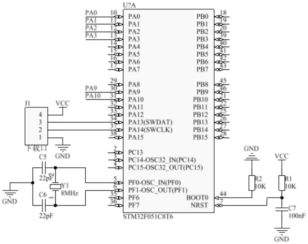
[0032] The wireless communication unit of this embodiment is mainly composed of an NB communication module, a control chip, a control circuit, a lock execution circuit, and a wakeup execution circuit. The control chip of this embodiment adopts the STM32F051C8T6 chip, see image 3. Such as Figure 4 , NB communication module is composed of NB communication chip connected with SIM card socket. The SIM card socket is connected through the NB communication chip to communicate with the control chip. The wireless communication unit is arranged in the corresponding area 34 of the housing 0, and the battery 37 is next to the area 34. The NB communication chip used in this embodiment is the NBT23 chip.
[0033] In this embodiment, the control circuit is a reed switch 10, and the reed switch 10 communicates with the control chip, see Picture 10. The lock ring 8 is installed on the storage device through a mounting plate 7. The mounting plate 71 is provided with a magnet (not shown in the figure) at a position corresponding to the reed pipe when the escort bed is in the storage state (corresponding to the boss at the lower part of the mounting plate 81). A positioning step is provided in the middle of the mounting plate 7, and the lock ring is connected to the mounting plate 7 through a connecting plate 81. The mounting plate 7 and the connecting plate 81 are provided with corresponding connecting holes, and the connection between the two is realized by passing a screw in the connecting hole, and the alignment of the magnet and the reed switch 10 is completed. The reed switch 10 of this embodiment can also be replaced with a high-cost Hall sensor as another alternative implementation. The function of the control circuit can also be achieved by using a light sensor. The technical means mentioned in the above-mentioned implementations are all Those in the field can be implemented, so I won’t repeat them here.
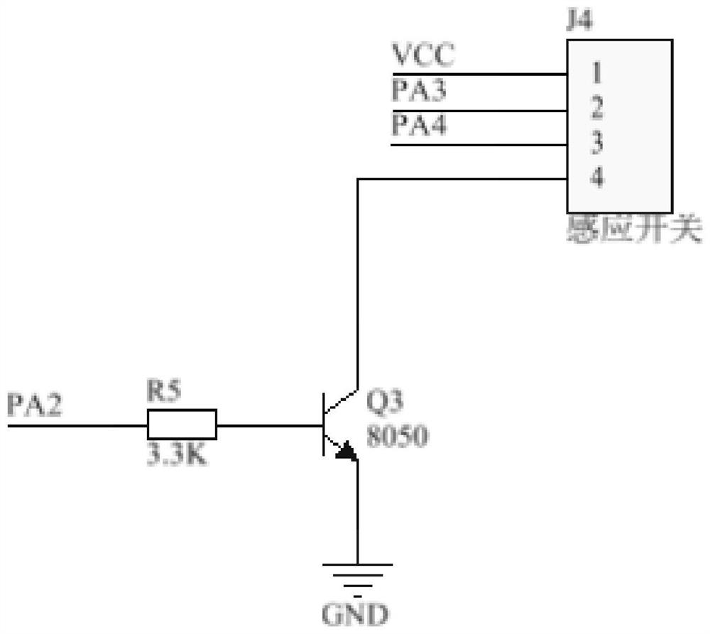
[0034] Such as figure 2 The wake-up execution circuit includes a resistor R5 and a transistor Q3. The wake-up device is connected to the collector of the transistor Q3, and the base of the transistor Q3 is communicatively connected to the control chip through the resistor R5. The function of the wake-up execution circuit is to realize the "reset" operation of the wake-up device when the lock device is locked.
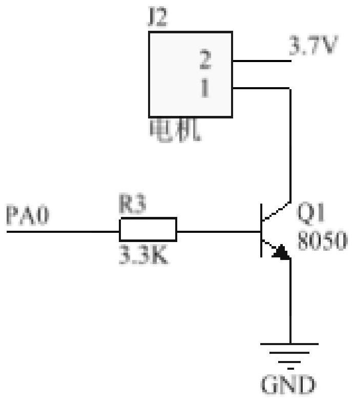
[0035] Such as figure 1 , The lock execution circuit is connected to the motor in communication. The lock execution circuit is composed of a load resistor R3 and a transistor Q1. The base of the transistor Q1 is communicatively connected with the control chip through the load resistor R3.
[0036] The lock device of this embodiment also includes an unlock prompt circuit, see Image 6 , The unlock prompt circuit is mainly composed of a buzzer and a transistor. The buzzer is connected to the collector of the transistor Q2, and the base of the transistor Q2 is in communication with the control chip through a resistor R4.
[0037] Such as Figure 5 The lock device of this embodiment also includes a transformer circuit, which is composed of an XC6203 chip connected to capacitors C1, C2, C3, and C4 to achieve a DC voltage output of 3.7v.
[0038] Such as Picture 9 The lock device of this embodiment also includes a wake-up device, which is arranged on the bed frame of the nursing bed. The wake-up device is mainly composed of a touch panel 95, a conductive sponge 94, and a capacitive sensor 92. The touch panel 95 is connected to the capacitive sensing touch device 92 through the conductive sponge 94, and the capacitive sensing touch device communicates with the control chip through the wake-up execution circuit. In this embodiment, the touch pad 165 adopts an acrylic panel, and the capacitive sensor touch device 162 is installed in a fixing member composed of a plastic housing 163 and a mounting bracket 161, see Picture 9. The fixing piece is arranged on the bed frame.
[0039] In the escort bed of this embodiment, a logo indicating the wake-up lock device is affixed to the corresponding position of the bed frame. When the user needs to wake up the lock device, touch the marking area, the bed frame triggers a working signal from the wake-up execution circuit to the control chip in the lock device through the conductive rubber, and the lock device is energized and enters the working state. At this time, the lock device is in a waiting state until the user scans the QR code or barcode with payment information on the bed frame, and after completing the registration, recharge and other operations, the server sends a work instruction to the lock device, and the lock device passes through the wireless communication unit. The work instruction received by the NB communication module completes the unlocking action so that the user can take away the escort bed. Similarly, when the user finishes using the escort bed and puts the escort bed into the storage device, after the above-mentioned touch switch in the lock device collects the corresponding trigger signal, it sends a use stop signal to the remote server through the NB communication module, and it is completed Timing of the use process, settlement of use rent.
[0040] The accompany bed storage cabinet of this embodiment adopts the lock device of the present invention to facilitate remote management, convenient use, and saves human resources in hospitals and health stations.
[0041] On the other hand, by designing the wake-up device and corresponding control circuit specially suitable for the escort bed storage cabinet, the standby time of the escort bed storage cabinet has been greatly increased, which is convenient for maintenance; further by adding anti-theft control The circuit solves the user's embezzlement problem; the lock device is changed from being set on the storage device to being set on the accompany bed, which improves the convenience in the process of renting the accompany bed.
[0042] The above are only preferred specific embodiments of the present invention, but the protection scope of the present invention is not limited to this. Any person skilled in the art can easily think of changes or changes within the technical scope disclosed by the present invention. All replacements shall be covered within the protection scope of the present invention. Therefore, the protection scope of the present invention should be subject to the protection scope of the claims.

PUM

no PUM

Description & Claims & Application Information

We can also present the details of the Description, Claims and Application information to help users get a comprehensive understanding of the technical details of the patent, such as background art, summary of invention, brief description of drawings, description of embodiments, and other original content. On the other hand, users can also determine the specific scope of protection of the technology through the list of claims; as well as understand the changes in the life cycle of the technology with the presentation of the patent timeline. Login to view more.

Similar technology patents

Payment method, payment device and wearable device

Owner:YULONG COMPUTER TELECOMM SCI (SHENZHEN) CO LTD

Network scanning system

InactiveUS20050057780A1improve conveniencelow cost
Owner:CANON DENSHI KK

Classification and recommendation of technical efficacy words

  • Improve convenience
Why Eureka
Try Eureka