Battery mounting and fixing structure for battery box of new energy automobile

A new energy vehicle and fixed structure technology, applied in the direction of battery/battery traction, battery, structural parts, etc., can solve the problems of inconvenient battery disassembly, reduced service life of lithium battery, friction and collision, etc., to improve heat dissipation effect and improve work efficiency Efficiency and the effect of increasing the service life

Active Publication Date: 2020-09-04
湖北一特新能源有限公司
View PDF7 Cites 2 Cited by
  • Summary
  • Abstract
  • Description
  • Claims
  • Application Information

AI Technical Summary

Problems solved by technology

[0002] New energy vehicles have gradually entered the public's field of vision due to their green and environmentally friendly features. Automotive lithium batteries are an essential part of the car, providing energy for the operation of the car. During the driving process, especially on rugged mountain roads, the car Violent shaking will cause friction and collision between other parts of the car and the lithium battery, which will reduce the service life of the lithium battery, so the lithium battery is generally fixed in the battery box
[0003] The existing battery is fixedly installed in the battery box, which is inconvenient for the battery to be disassembled. In addition, the battery is in contact with the inner wall of the battery box, which not only has no anti-collision effect on the battery, reduces the service life of the battery, but also affects the battery life. heat radiation

Method used


Image

  • Battery mounting and fixing structure for battery box of new energy automobile
  • Battery mounting and fixing structure for battery box of new energy automobile
  • Battery mounting and fixing structure for battery box of new energy automobile

Examples


Embodiment Construction

[0024] The following will clearly and completely describe the technical solutions in the embodiments of the present invention with reference to the accompanying drawings in the embodiments of the present invention. Obviously, the described embodiments are only some, not all, embodiments of the present invention.

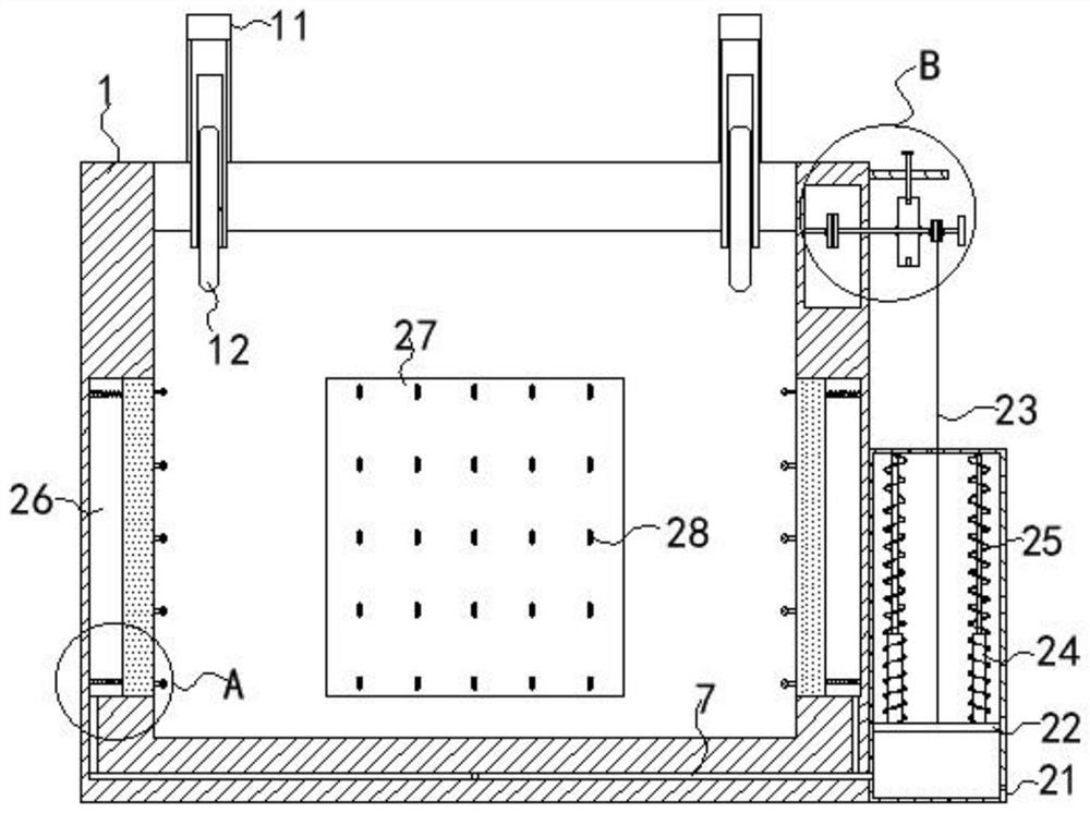
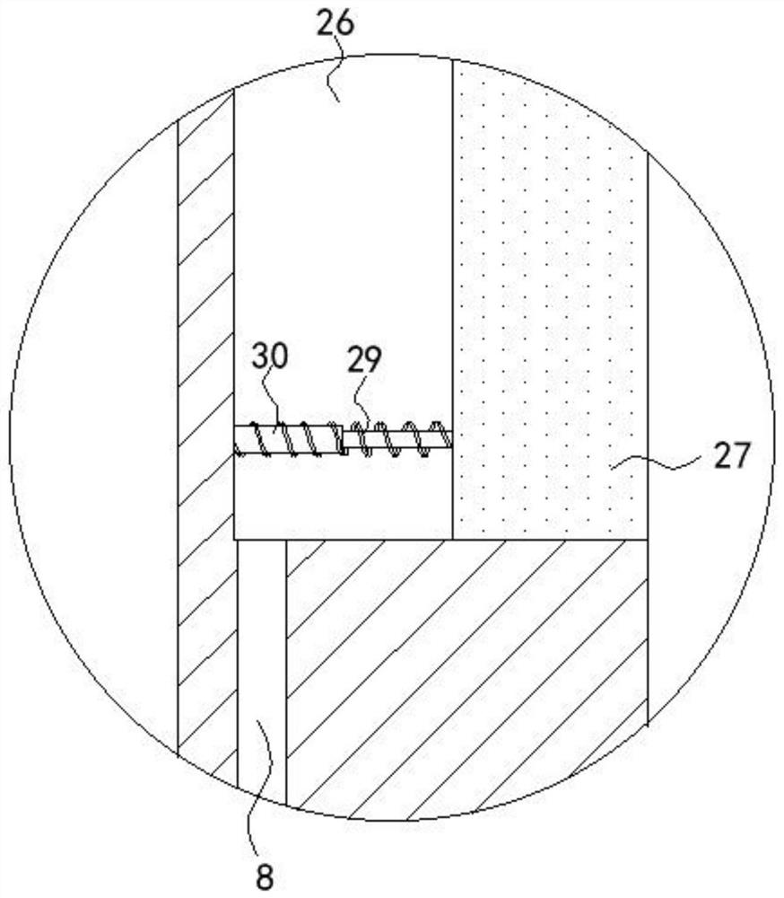
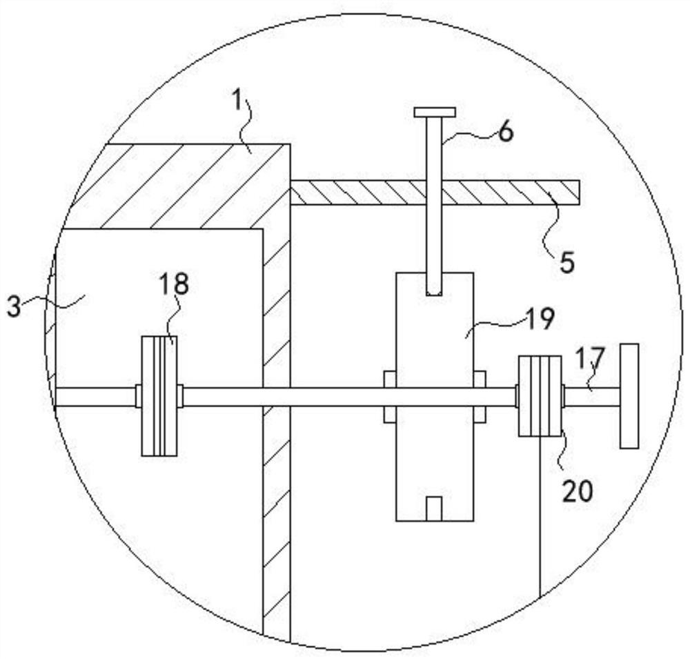
[0025] refer to Figure 1-6 , a new energy vehicle battery box battery installation and fixing structure, including a box body 1, a first chamber 2 is provided in the side walls of the front and rear ends of the box body 1, and two chambers are arranged in the right side wall of the box body 1. The first chamber 2 is connected to the second chamber 3, the inner wall of the first chamber 2 is provided with a plurality of fixed pulleys 4, the bottom of the first chamber 2 is provided with a fixing mechanism, and the fixed end of the fixing mechanism runs through the first chamber. The top surface of the chamber 2 is set and extends to the outside, a plurality of first ...


PUM


Abstract

The invention discloses a battery mounting and fixing structure for a battery box of a new energy automobile. The structure comprises a box body, and first cavities are formed in the side walls of thefront end and the rear end of the box body. A second cavity communicated with the two first cavities is formed in the side wall of the right end of the box body; a plurality of fixed pulleys are arranged on the inner wall of the first cavities; fixing mechanisms are arranged at the bottom of the first cavities; the fixed ends of the fixing mechanisms penetrate through the top surfaces of the first cavities and extend to the outside of the first cavities; and a plurality of first elastic assemblies are fixedly connected between the fixing mechanisms and the inner walls of the first cavities. Acontrol mechanism is rotatably arranged on the side wall of the second cavity in a penetrating mode, the control end of the control mechanism sequentially penetrates through the fixed pulleys in a sliding mode and is fixedly connected with the fixing mechanisms, a positioning mechanism movably connected with the control mechanism is arranged on the side wall of the box body, and a pneumatic control mechanism is fixedly connected to the side wall of the box body below the control mechanism. According to the invention, the battery is convenient to mount and dismount, and the anti-collision performance and the heat dissipation performance of the battery can be effectively improved.

Description

technical field [0001] The invention relates to the technical field of new energy vehicles, in particular to a battery installation and fixing structure of a battery box of a new energy vehicle. Background technique [0002] New energy vehicles have gradually entered the public's field of vision due to their green and environmentally friendly features. Automotive lithium batteries are an essential part of the car, providing energy for the operation of the car. During the driving process, especially on rugged mountain roads, the car Violent shaking will cause friction and collision between other parts of the car and the lithium battery, which will reduce the service life of the lithium battery, so the lithium battery is generally fixed in the battery box. [0003] The existing battery is fixedly installed in the battery box, which is inconvenient for the battery to be disassembled. In addition, the battery is in contact with the inner wall of the battery box, which not only h...

Claims


Application Information

Patent Timeline
Patent Type & Authority Applications(China)
IPC IPC(8): H01M2/10B60L50/64H01M50/20
CPCB60L50/64H01M2220/20Y02E60/10Y02T10/70
Inventor 王金明
Owner 湖北一特新能源有限公司
Why Eureka
Try Eureka