Massage chair and massage movement thereof
A technology of movement and movement frame, applied in vibration massage, roller massage, massage auxiliary products, etc., can solve the problems of increasing the volume of the massage movement, affecting the user's comfort, and small adjustment range of the massage movement. , to achieve the effect of simplifying the structure, facilitating the layout and reducing the volume
- Summary
- Abstract
- Description
- Claims
- Application Information
AI Technical Summary
Problems solved by technology
Method used
Image
Examples
Embodiment 1
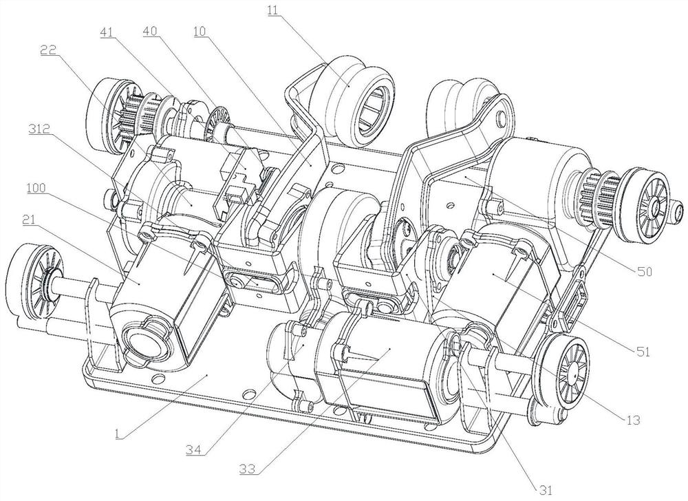
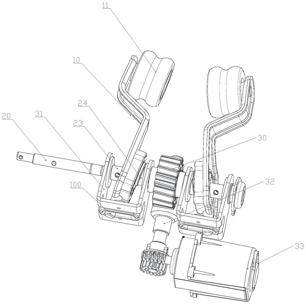
[0040] Such as Figure 1-7 The massage movement shown includes a movement frame 1 and two massage arms 10 arranged on the left and right and a kneading assembly installed on the movement frame 1. The kneading assembly includes a movement frame 1 installed on the movement frame 1. The kneading shaft 20 and the first motor 21 on the upper side, the massage crank 10 is sleeved on the kneading shaft 20 and can rotate, the top of the massage crank 10 is equipped with a massage roller 11, and the first motor 21 drives the kneading shaft 20. Rotate and make the massage rollers 11 on the two massage arms 10 approach or move away from each other to realize the kneading action. The massage rollers 11 can be directly rotatably installed on the massage arms 10 through the rotating shaft. The publication number is the installation method of the massage roller 11 in CN109620672A; the massage roller 11 can be a non-magnetic roller or a magnetic roller.
[0041] In this embodiment, it also incl...
Embodiment approach
[0046] Such as Figure 5 The rotating base 31 shown is the first implementation in this embodiment: the entire rotating base 31 is directly injection-molded, and the connecting wall 319 of the rotating base 31 is provided with a rounded rectangular first through hole, the first The through hole is the limiting groove 312, and this arrangement makes the processing simple and low cost.
[0047] Such as Image 6 The rotating base 31 shown is the second implementation in this embodiment: the connecting wall 319 of the rotating base 31 is provided with a second through hole, and the connecting wall 319 of the rotating base 31 is also fixedly installed with a connecting piece 313, the The connecting member 313 is provided with a third through hole with a rounded rectangular shape. The third through hole is the limiting groove 312, wherein the side wall of the third through hole passes through the second through hole and abuts against the second through hole. Hole on. This arrangement ...
Embodiment 2
[0058] The difference between this embodiment and the first embodiment is that a knocking component is also provided in this embodiment.
[0059] In this embodiment, a percussion shaft and a percussion motor are installed on the rotating seat, and two percussion linkages are sleeved on the percussion shaft, and the two percussion linkages are respectively connected with two massage crank arms. The motor drives the percussion shaft to rotate to drive the two massage crank arms to perform percussion actions, and the second motor mounted on the movement frame drives the rotating base to rotate, thereby driving the massage crank arms to rotate around the kneading shaft.
[0060] With this arrangement, the percussion assembly is installed on the rotating seat, so that during the adjustment process of the massage crank, there is no relative movement between the percussion assembly and the massage crank, so that no matter how the massage crank is adjusted to any angle, the The striking co...
PUM
 Abstract
Description
Claims
Application Information
 - R&D
- Intellectual Property
- Life Sciences
- Materials
- Tech Scout
- Unparalleled Data Quality
- Higher Quality Content
- 60% Fewer Hallucinations
Browse by: Latest US Patents, China's latest patents, Technical Efficacy Thesaurus, Application Domain, Technology Topic, Popular Technical Reports.
© 2025 PatSnap. All rights reserved.Legal|Privacy policy|Modern Slavery Act Transparency Statement|Sitemap|About US| Contact US: help@patsnap.com


