A super high pressure stone water jet cutting machine

A cutting machine, stone water technology, applied in the direction of stone processing tools, stone processing equipment, work accessories, etc., can solve the problems of reduced cleaning efficiency, damage to equipment parts, and sludge not cleaned up in time

Active Publication Date: 2022-03-29
广东龙美达建材有限公司
View PDF7 Cites 0 Cited by
  • Summary
  • Abstract
  • Description
  • Claims
  • Application Information

AI Technical Summary

Problems solved by technology

[0003] In the prior art, multiple nozzle holes are arranged in a circle and the peeling effect is the best during high-pressure spraying, but the residual sludge after peeling is not cleaned up in time, which reduces the cleaning efficiency. Multiple nozzle holes are arranged in a circle and sprayed to reduce the heat generated during cutting. The cooling range is small, and the high temperature will cause certain damage to the equipment components

Method used


Image

  • A super high pressure stone water jet cutting machine
  • A super high pressure stone water jet cutting machine
  • A super high pressure stone water jet cutting machine

Examples


Embodiment 1

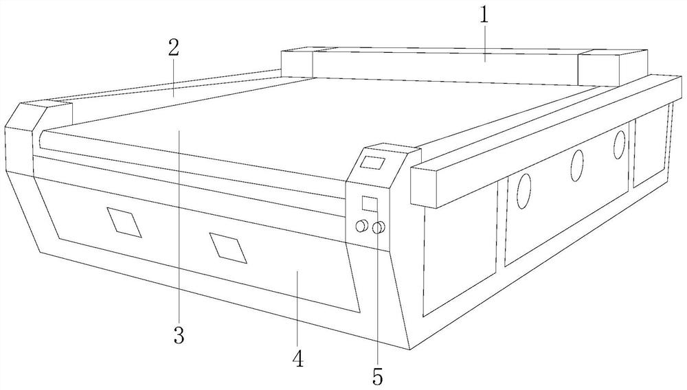
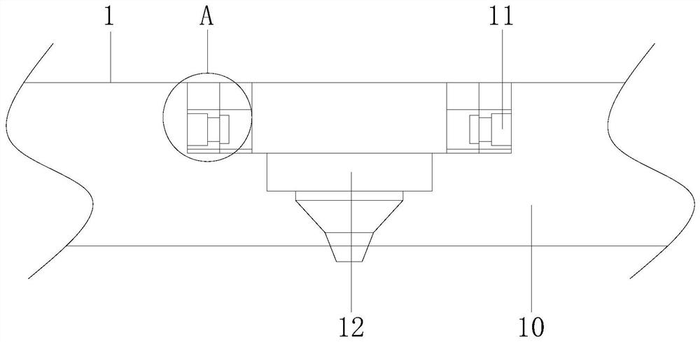
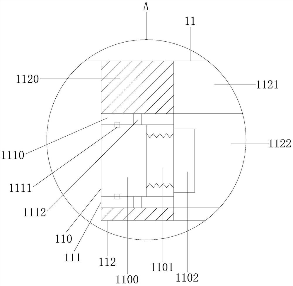
[0026] Example 1 see Figure 1-6 , the present invention provides a technical solution for an ultra-high pressure stone water jet cutting machine: its structure includes a cutting frame 1, a lifting side frame 2, a conveying table 3, a cutting machine frame 4, and a controller 5, and the lifting side frame 2 realizes The cutting frame 1 is lifted and adjusted to cut depth and water mist spraying height distance, the cutting frame 1 is installed and connected with the lifting side frame 2, the delivery table 3 is installed on the cutting machine frame 4, and the cutting machine frame 4. A controller 5 is installed. The cutting frame 1 is composed of a mobile main frame 10, a water spray device 11, and a cutting head 12. Installed and connected with the cutting machine head 12, the water spray device 11 includes a spraying machine head 110, a moving turntable 111, and a spray frame 112, and the spraying machine head 110 is installed on the spray frame 112, and the moving turntab...

Embodiment 2

[0028] Example 2 see Figure 7, the present invention provides a technical solution for an ultra-high pressure stone water jet cutting machine: the structure of the spray structure 610 includes a spray swivel 6100, a structural mounting plate 6101, a low-pressure water sprayer 6102, and a mist spray fan 6103. The spray structure 610 There are more than 3 and are arranged in a ring shape, so that the water spray rotates in a spiral shape to clean up the dirt after peeling off in a large range. There are low-pressure water sprayers 6102 and mist spray fans 6103, and the mist spray fans 6103 are used to spray cooling air for cooling.

[0029] The spray structure 610 is installed on the water spray ring 61, and there are more than 3 and arranged in a ring shape to clean up the dirt after peeling off in a large range. The water spray ring 61 rotates to make the water spray rotate in a spiral shape to clean the sludge. At this time, the mist blower 6103 sprays cooling air for cooli...


PUM


Abstract

The invention discloses an ultra-high pressure water jet cutting machine for stone materials. On the cutting machine frame, the cutting machine frame is equipped with a controller. The cutting frame is composed of a mobile main frame, a water spray device, and a cutting head. Connected, the water spraying device includes a spraying main engine head, a moving turntable, and a spraying frame. The spraying main machine head is installed on the spraying frame. The high-pressure spraying of the circular spraying head of the present invention peels off stubborn dirt, and the high-pressure micro fan blows out cold air to assist cooling. The water spraying ring Clean the peeled dirt in a wide range to achieve the highest pressure spray and the sludge can also be cleaned in time. The low-pressure water sprayer sprays mist along with the cold wind of the mist spray fan to extend the blowing distance to achieve large-scale cooling.

Description

technical field [0001] The invention relates to the field of processing machinery, in particular to an ultra-high pressure stone water jet cutting machine. Background technique [0002] Ultra-high pressure water jet cleaning technology can completely remove deposits regardless of the structure. It uses water as the medium to drive a large-flow supercharger through a diesel unit or an electric unit, and uses the kinetic energy of high-speed water jets to peel off stubborn dirt on the surface; when cutting stone In order to improve the cleaning effect, the nozzle is adjusted so that multiple nozzle holes are arranged in a circular state to spray out to achieve the highest pressure spray. [0003] In the prior art, multiple nozzle holes are arranged in a circle and the peeling effect is the best during high-pressure spraying, but the residual sludge after peeling is not cleaned up in time, which reduces the cleaning efficiency. Multiple nozzle holes are arranged in a circle and...

Claims


Application Information

Patent Timeline
Patent Type & Authority Patents(China)
IPC IPC(8): B28D1/00B28D7/00B28D7/02B26F3/00
CPCB28D1/00B28D7/00B28D7/02B26F3/004
Inventor 赖太忠
Owner 广东龙美达建材有限公司
Why Eureka
Try Eureka