Metal part code pressing mechanism capable of adjusting letters

A metal component and adjustable technology, which is applied in the field of stamping mechanism, can solve problems such as the loosening of the fixed structure of the code sheet, the trouble of mold replacement, and the inability to change the code, so as to achieve the effects of reasonable structural design, improved service life and reduced loss

Inactive Publication Date: 2020-09-08
内蒙古钧恒科技有限责任公司
View PDF15 Cites 0 Cited by
  • Summary
  • Abstract
  • Description
  • Claims
  • Application Information

AI Technical Summary

Problems solved by technology

[0002] In the process of industrial production, codes are often printed on the workpiece according to the demand. The traditional printing method is to use the hydraulic cylinder to drive the mold for stamping, and use the stamping method to press the code on the surface of the workpiece; because the code printing sequence of different workpieces is different. They are not the same, so when punching different workpieces, it is necessary to replace the corresponding mold. The traditional molds are all fixed versions, and the codes on the molds are all fixed. This kind of fixed version of the mold is very troublesome to replace, and because The code cannot be changed. Once the character code on the mold is different from the required character code, it cannot be used. The mold can only be remade, which is a waste of resources.
[0003] In order to solve the above-mentioned technical problems, those skilled in the art have designed a movable mold formed by superimposing a plurality of character code sheets, and the staff can adjust the character code chips as required to obtain the required character code combination; however, this method There is also a defect, that is, every time you adjust the character code combination, you must loosen the fixed structure of the character code chip, and then re-tighten and fix it after the adjustment is completed. Although this process is simple, it still cannot meet the increasingly efficient requirements. Industrial Production Demand

Method used


Image

  • Metal part code pressing mechanism capable of adjusting letters
  • Metal part code pressing mechanism capable of adjusting letters
  • Metal part code pressing mechanism capable of adjusting letters

Examples


Embodiment Construction

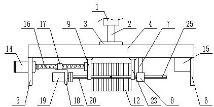
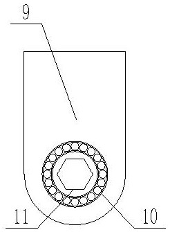
[0029] The present invention is specifically described below in conjunction with accompanying drawing, as Figure 1-6 As shown, the inventive point of the present application is that the vertical rod 7 is fixedly installed on the lower surface of the mounting base, the vertical rod is perpendicular to the lower surface of the mounting base, and the vertical rod is located between the first mounting plate and the second mounting plate. The lower end of the vertical pole is fixedly connected with the outer circular inner hexagonal steel pipe 8, and the lower surface of the mounting seat is fixedly installed with a support plate 9 and a support plate 2 23, and the support plate 1 and the support plate 2 are all parallel to the mounting plate 1, and the support plate 1 and the support plate 2 are all parallel to the mounting plate 1. Plate one and support plate two are positioned between vertical rod and mounting plate one, and support plate one is close to mounting plate one, and ...


PUM


Abstract

The invention discloses a metal part code pressing mechanism capable of adjusting letters. The metal part code pressing mechanism comprises a hydraulic cylinder. A telescopic rod of the hydraulic cylinder is vertically downward. The lower end of the telescopic rod is fixedly connected with a mounting seat through a flange, a first mounting plate and a second mounting plate are fixedly connected tothe lower surface of the mounting seat, the first mounting plate is located at the left end of the lower surface of the mounting seat, the second mounting plate is located at the right end of the lower surface of the mounting seat, the first mounting plate is parallel to the second mounting plate, and the first mounting plate and the second mounting plate are both vertical to the lower surface ofthe mounting seat. The metal part code pressing mechanism has the beneficial effects that the technical effect of automatically converting codes is achieved through a servo motor, the structural design is reasonable, and the structural losses of the device are effectively reduced.

Description

technical field [0001] The invention relates to the technical field of stamping mechanisms, in particular to an adjustable letter pressing mechanism for metal parts. Background technique [0002] In the process of industrial production, codes are often printed on the workpiece according to the demand. The traditional printing method is to use the hydraulic cylinder to drive the mold for stamping, and use the stamping method to press the code on the surface of the workpiece; because the code printing sequence of different workpieces is different. They are not the same, so when punching different workpieces, it is necessary to replace the corresponding mold. The traditional molds are all fixed versions, and the codes on the molds are all fixed. This kind of fixed version of the mold is very troublesome to replace, and because The code cannot be changed. Once the character code on the mold is different from the required character code, it cannot be used, and the mold can only b...

Claims


Application Information

Patent Timeline
Patent Type & Authority Applications(China)
IPC IPC(8): B41K3/12B41K3/62
CPCB41K3/125B41K3/62
Inventor 王萍
Owner 内蒙古钧恒科技有限责任公司
Why Eureka
Try Eureka