A power cable pay-off device

A pay-off device and power cable technology, which is applied in the field of power cables, can solve the problems of inconvenient cable fixing, waste, and simple structure, and achieve the effects of precise pay-off length, avoiding waste of cables, and strong practicability

Active Publication Date: 2021-09-17
上海闸电东海电力工程有限公司
View PDF6 Cites 0 Cited by
  • Summary
  • Abstract
  • Description
  • Claims
  • Application Information

AI Technical Summary

Problems solved by technology

[0004] The purpose of the present invention is to provide a power cable pay-off device to at least solve the problem that the existing pay-off device in the prior art has a relatively simple structure, is inconvenient to fix the cable, cannot accurately determine the length of the current pay-out cable, and is easy to problem of wasting

Method used


Image

  • A power cable pay-off device
  • A power cable pay-off device
  • A power cable pay-off device

Examples


Embodiment Construction

[0023] The following will clearly and completely describe the technical solutions in the embodiments of the present invention with reference to the accompanying drawings in the embodiments of the present invention. Obviously, the described embodiments are only some, not all, embodiments of the present invention. Based on the embodiments of the present invention, all other embodiments obtained by persons of ordinary skill in the art without making creative efforts belong to the protection scope of the present invention.

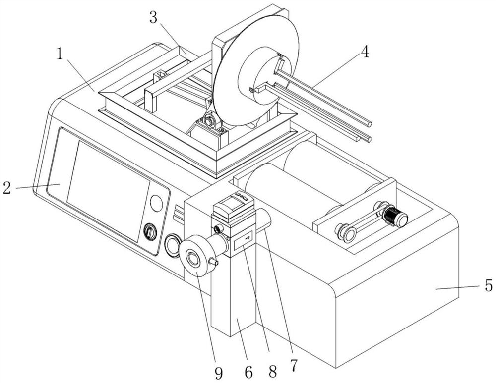
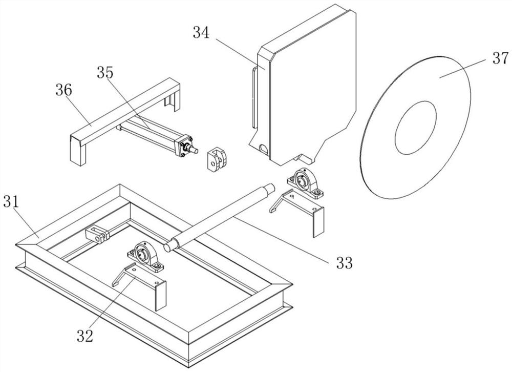
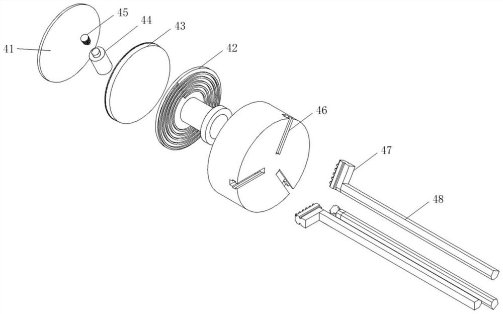
[0024] see Figure 1-4 , the present invention provides a technical solution: a power cable pay-off device, including: a base 1, a controller 2, a rotating mechanism 3, a fixing mechanism 4 and a rotating mechanism 5; the controller 2 is arranged on the base 1 along the left and right directions On the front side, the specific use signal of the controller 2 is purchased, installed and used directly from the market according to the specific use requirements. Th...


PUM


Abstract

The invention discloses a power cable pay-off device, comprising: a base, a controller, a rotating mechanism, a fixing mechanism and a rotating mechanism; the controller is arranged on the front side of the base along the left and right directions; On the top right side of the base; the fixing mechanism is installed on the right side of the rotating mechanism along the left-right direction; the rotating mechanism is arranged on the right side of the base along the left-right direction and is located directly below the fixing mechanism, and The front side of the mechanism is provided with an induction mechanism. The power cable pay-off device is relatively simple in structure for the existing pay-off device, it is not convenient to fix the cable, and it is impossible to accurately determine the length of the current pay-out cable, which is easy to cause waste, and can realize automatic cable pay-off At the same time, the monitoring of the length of the cable direction makes the pay-off length more accurate, thereby avoiding wasting cables, and it is convenient to fix the cables to reduce the operator's operation items, which is highly practical.

Description

technical field [0001] The invention relates to the technical field of power cables, in particular to a power cable pay-off device. Background technique [0002] A cable is usually a rope-like cable formed by twisting several or groups of wires [at least two in each group]. Each group of wires is insulated from each other and sealed by one or more mutually insulated conductive cores The insulated wire formed in the sheath is often twisted around a center, and the entire outside is covered with a highly insulating covering layer. It is mostly erected in the air or installed underground or underwater for telecommunications or power transmission, for transmission, Distribute electrical energy or transmit electrical signals. The difference between it and ordinary wires is that the cable size is larger and the structure is more complicated; [0003] In the field of prior art, the existing power cables on the market need to be wound together to form a finished cable reel during t...

Claims


Application Information

Patent Timeline
Patent Type & Authority Patents(China)
IPC IPC(8): B65H49/20B65H75/32
CPCB65H49/20B65H75/32
Inventor 徐小玉
Owner 上海闸电东海电力工程有限公司
Why Eureka
Try Eureka