Beam-form unified movable mould frame

A mobile formwork and two-in-one technology, which is applied in bridges, bridge construction, erection/assembly of bridges, etc., can solve the problems of increased construction costs and construction difficulties, and the inability to adapt to through-hole technology, so as to simplify the process and reduce investment Effect

Inactive Publication Date: 2008-06-25
CHINA MAJOR BRIDGE ENG
View PDF0 Cites 6 Cited by
  • Summary
  • Abstract
  • Description
  • Claims
  • Application Information

AI Technical Summary

Problems solved by technology

For bridges whose pier width is much larger than that of the concrete box girder bottom plate, the hole-through technology of conventional mobile formwork will not be able to adapt, even if it is barely done, it will greatly increase the construction cost and construction difficulty

Method used


Image

  • Beam-form unified movable mould frame
  • Beam-form unified movable mould frame
  • Beam-form unified movable mould frame

Examples


Embodiment Construction

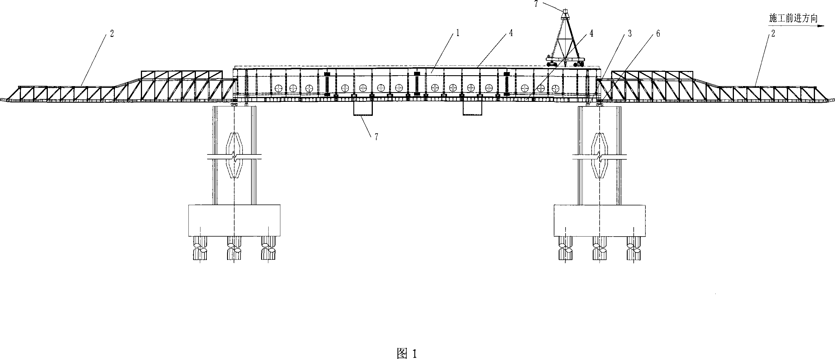
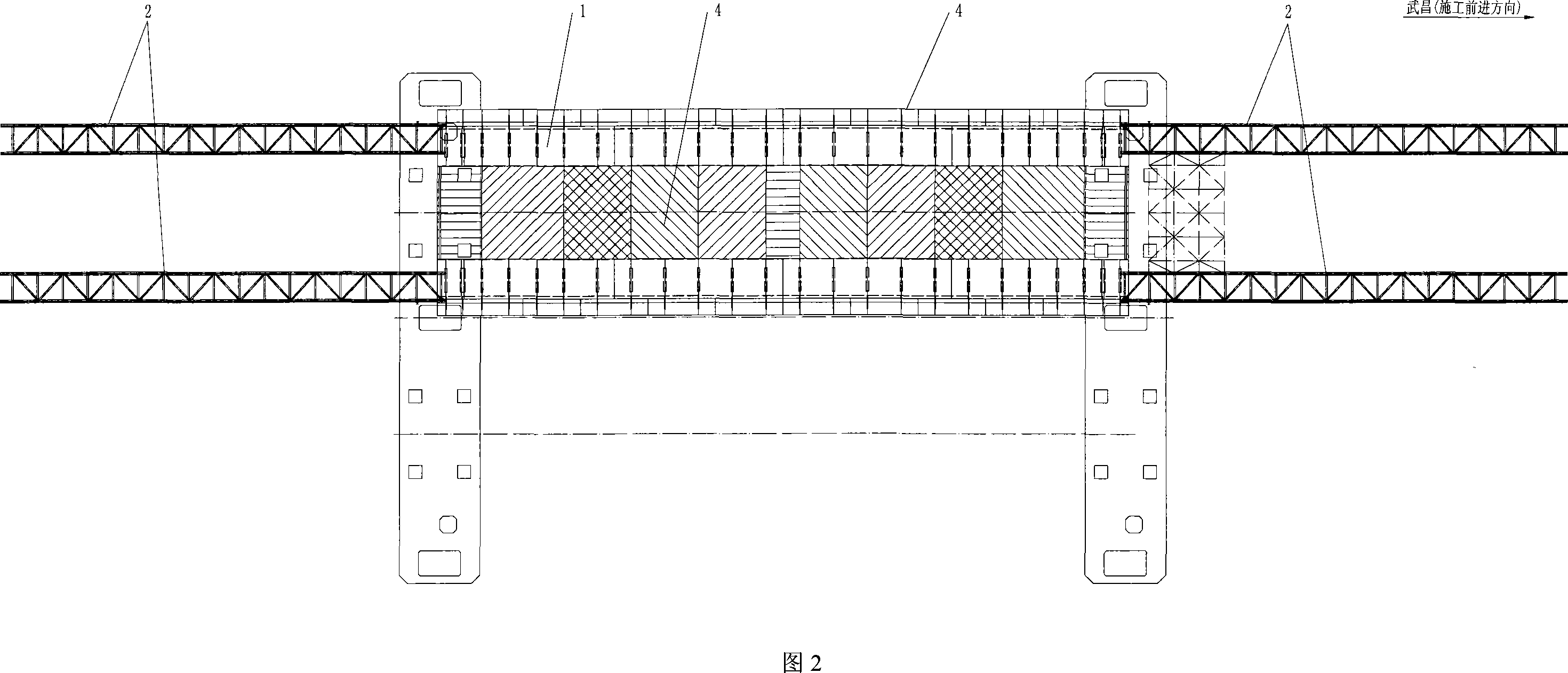
[0042] 1 and 2, the mobile formwork is composed of load-bearing main beam 1, guide beam 2, supporting device 3, formwork system 4, bottom mold opening and closing system 5, vertical and horizontal movement system 6 and auxiliary structure 7.

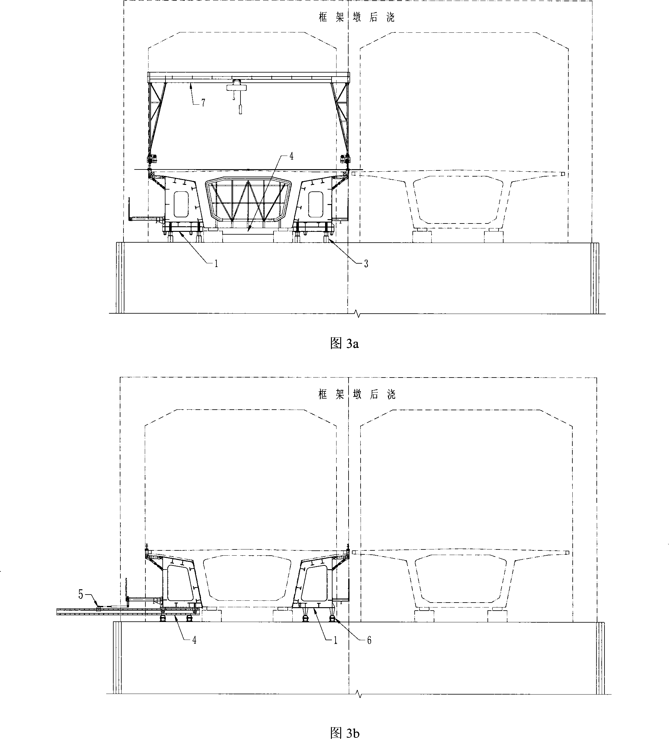
[0043] Referring to Fig. 3a, the main girder 1 of the mobile formwork is supported on the top of the pier through the supporting device 3. The door crane of the auxiliary structure 7 is arranged above the mobile formwork.

[0044] Referring to Fig. 3b, when the mobile formwork moves vertically, the bottom form 4 is opened horizontally through the bottom form opening and closing system 5, so as to avoid the bridge support pad stone on the top of the pier.

[0045] Referring to Fig. 3c, when the concrete of the box girder is poured, the bottom form 4 is hung on the main beam 1 by the suspender 8; the bottom form opening system 5 is attached to one side of the main beam 1.

[0046] Referring to Fig. 3d, when demoulding, the main girder 1 d...


PUM


Abstract

The invention discloses a beam-mold type movable die carrier which is large-scale construction equipment used in the construction of box beams of upper structures of bridges of railways and highways. A load-bearing beam of the movable die carrier is a special cross-section steel box, a top plate and an inner web of the movable die carrier are taken as external molds of a concrete box beam; a bottom die adopts a low height orthotropic plate structure and is opened and closed by single-side horizontal push. The beam-mold type movable die carrier is particularly suitable for construction under wide pier shaft conditions.

Description

technical field [0001] The invention relates to a bridge engineering superstructure box girder construction technology, in particular to a beam-mold-integrated mobile formwork used in cast-in-place concrete box girders. Background technique [0002] The technology of pouring concrete box girder with moving formwork has been widely used in our country. The formwork system and the load-bearing beam system of the conventional mobile formwork are separated. When traveling through the hole, the formwork system (especially the bottom formwork system) will be divided into two in the direction of the bridge, and they will be moved to the pier body on both sides. Outside the width range, use the gaps on both sides of the pier body to pass through. The prerequisite for the above-mentioned mobile formwork construction to be realized is that the width of the pier body is similar to the width of the bottom plate of the concrete box girder. For bridges whose ...

Claims


Application Information

Patent Timeline
Patent Type & Authority Applications(China)
IPC IPC(8): E01D21/00
Inventor 秦顺全李军堂潘东发周外男毛伟琦马涛张瑞霞刘翠云胡汉舟周超舟涂满明贾卫中
Owner CHINA MAJOR BRIDGE ENG
Why Eureka
Try Eureka