Cable unwinding rack

A pay-off frame and cable technology, which is applied in the direction of conveying filamentous materials, thin material handling, transportation and packaging, etc., to achieve the effect of easy sliding, improving stability and avoiding shaking

Inactive Publication Date: 2017-07-07
JIAXING GANKUN IND DESIGN
View PDF10 Cites 7 Cited by
  • Summary
  • Abstract
  • Description
  • Claims
  • Application Information

AI Technical Summary

Problems solved by technology

In the prior art, there is a lack of a cable pay-off mecha

Method used


Image

  • Cable unwinding rack
  • Cable unwinding rack
  • Cable unwinding rack

Examples


Embodiment 1

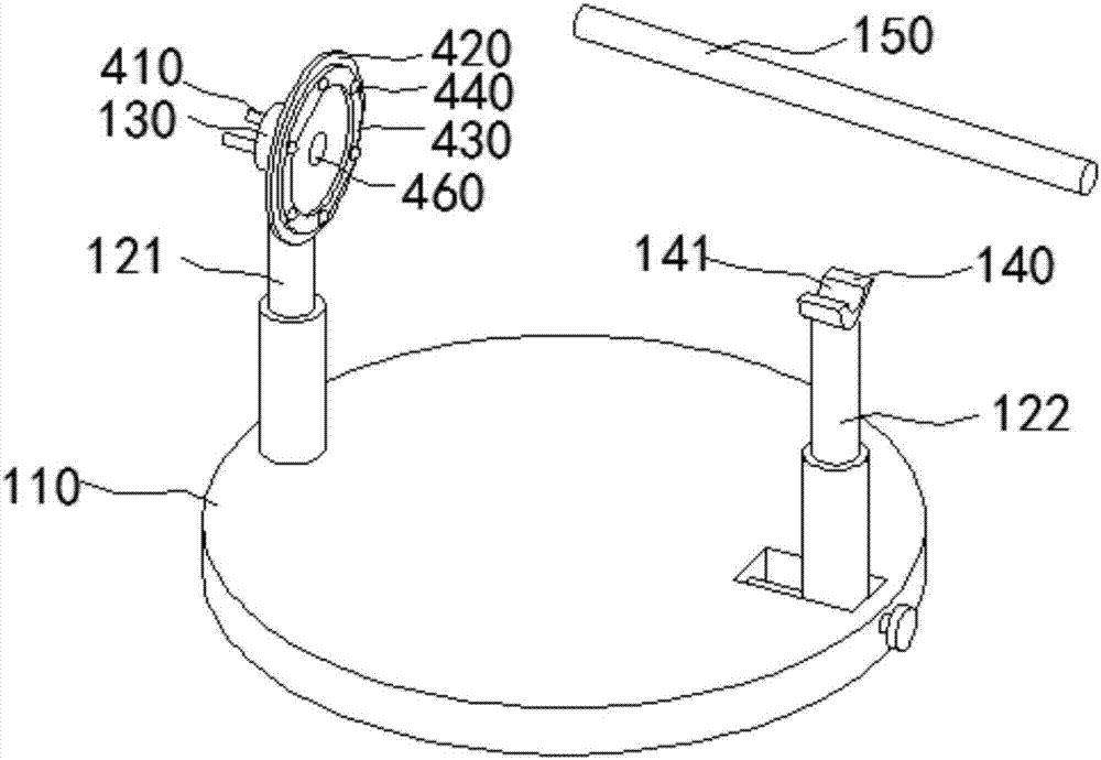
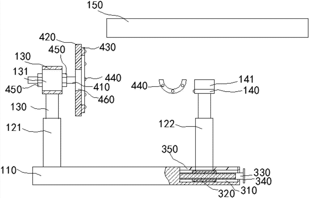
[0026] Such as Figure 1~3 As shown, the present embodiment provides a cable pay-off rack, which includes a base 110, a first support rod 121 and a second support rod 122 are vertically provided above the base 110; Seat 130, the first mounting seat 130 is rotatably connected with the first support rod 121 along the circumferential direction of the first support rod 121; the second support rod 122 top is provided with a second mounting seat 140, and the second mounting seat 140 is connected with the second supporting rod The rod 122 is fixedly connected; the first mounting seat 130 and the second mounting seat 140 are provided with a bearing cross bar 150 for carrying the cable tray, and the first mounting seat 130 is provided with an installation channel for matching with the corresponding end of the bearing cross bar 150 The hole 131, the second mounting seat 140 is provided with a mounting groove 141 for matching with the corresponding end of the bearing cross bar 150;

[0...


PUM


Abstract

The invention relates to the technical field of cable unwinding equipment, in particular to a cable unwinding rack. The cable unwinding rack comprises a first supporting rod and a second supporting rod which are vertically arranged above a base. The top end of the first supporting rod is provided with a first mounting base, and the top end of the second supporting rod is provided with a second mounting base. A bearing cross rod used for bearing a cable reel is arranged between the first mounting base and the second mounting base. The base is provided with a strip-shaped groove rail with an upward opening. The strip-shaped groove rail is internally provided with a first threaded rod which is sleeved with a mobile block. The mobile block is in threaded fit with the threaded rod. The bottom end of the second supporting rod is connected with the mobile block. A pressing disc is arranged on the side, facing the second mounting base, of the first mounting base and connected with the first mounting base through one or more adjustment screws which penetrate through the first mounting base, and adjustment nuts are all in threaded connection with the portions, on the two sides of the first mounting base, of the adjustment screws. A pressing disc through hole used for allowing the bearing cross rod to penetrate through is formed in the portion, corresponding to a mounting through hole, of the pressing disc. The cable unwinding rack can be well matched with cable reels of various sizes.

Description

technical field [0001] The invention relates to the technical field of cable pay-off equipment, in particular to a cable pay-off frame. Background technique [0002] According to the application, the cable pay-off rack is also called: cable reel bracket, wire spool rack, cable pay-off bracket, etc. According to the lifting form, it can be divided into hydraulic cable pay-off stand and mechanical cable pay-off stand. According to the use and structure, it can be divided into adjustable hydraulic pay-off rack, column-type pay-off rack, push-rod cable pay-off rack, horizontal cable reel rack, foot brake cable pay-off rack, and detachable cable pay-off rack. Rack, tension pay-off rack. According to the load capacity, it is divided into: 3T cable pay-off rack, 5T cable pay-off rack, 10T cable pay-off rack, 15T cable reel support, 20T cable reel support and larger tonnage cable reel support. [0003] The applicable cable reel diameter range of the cable reel bracket is 600mm-38...

Claims


Application Information

Patent Timeline
IPC IPC(8): B65H49/30
CPCB65H49/30B65H2701/34
Inventor 陆淼陆根法
Owner JIAXING GANKUN IND DESIGN
Why Eureka
Try Eureka