
Slicing device capable of adjusting thickness

A technology of slicing device and thickness adjustment, applied in metal processing and other directions, can solve the problems of troublesome sample feeding and unloading, high price, sliding, etc., to achieve the effect of adjustable thickness

Inactive Publication Date: 2016-02-24
XI AN JIAOTONG UNIV
View PDF10 Cites 20 Cited by
  • Summary
  • Abstract
  • Description
  • Claims
  • Application Information

AI Technical Summary

Problems solved by technology

Although there are a considerable number of sponge cutting machines at present, and the cutting blades do not need to be replaced, these devices themselves have problems such as complex structure, high price, and inconvenient use, and the feeding and unloading of samples is also troublesome.
The invention patent "Sponge Cutting Machine" with the application number 201210274237.X has simple structure and convenient operation, but there is no relevant introduction to ensure the uniformity of the thickness of the cut sponge and the positioning of the sponge sample; the invention patent with the application number 201320506479.7 "A Sponge Cutting device》is mainly used to cut cosmetic sponges with small volume. Although the cutting quality has been improved, the versatility of the device needs to be further strengthened.
In addition, there are also many slicing devices in the field of food processing, such as slicers for cutting fruits and vegetables. The invention patent of Patent No. 201110392043.5 "A Vegetable Slicer" cannot meet the needs of the market because the thickness of slices cannot be adjusted. No. 200810026948.9 invention patent "a slicer" proposes to adjust the thickness of slices by constantly changing the knife set, which is troublesome to operate
In addition, although some other patents can achieve the uniformity of slice thickness, there is no detailed introduction to the positioning of the cut object, and there may be phenomena such as sliding of the cut object during the cutting process

Method used


Image

  • Slicing device capable of adjusting thickness
  • Slicing device capable of adjusting thickness
  • Slicing device capable of adjusting thickness

Examples


Embodiment Construction

[0030] The present invention will be further described below in conjunction with accompanying drawing. But the content of the present invention is not limited thereto.

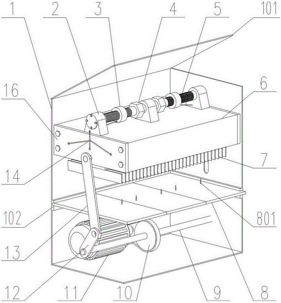
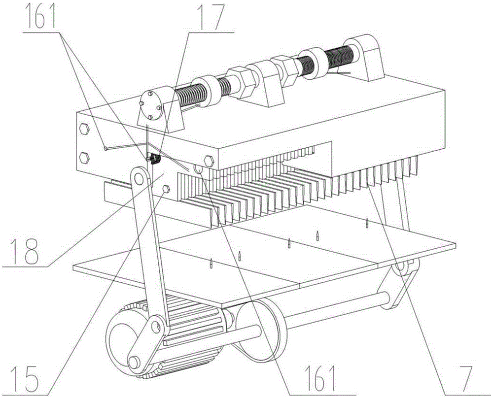
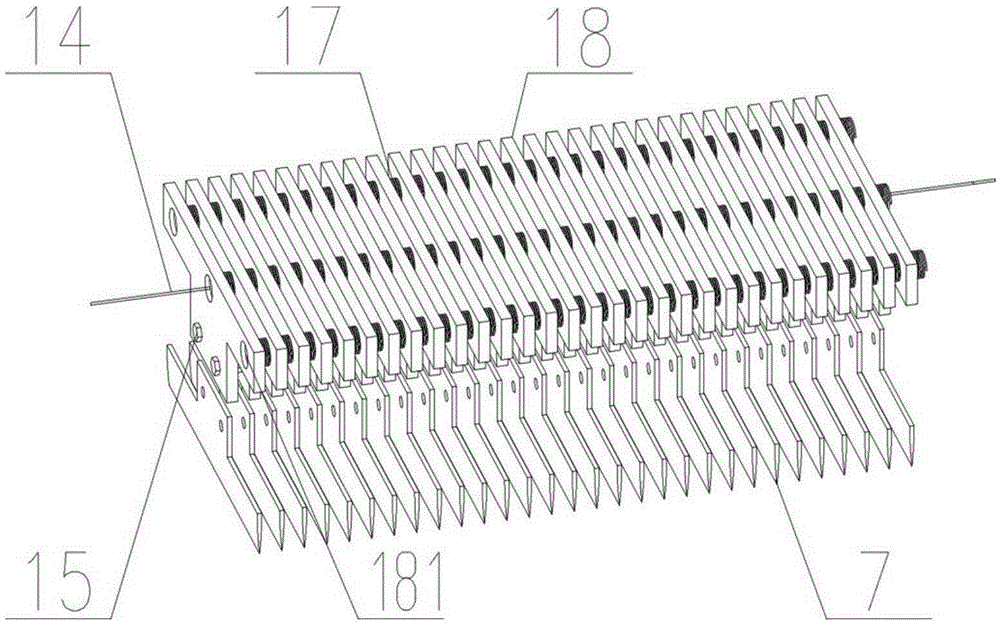
[0031] Such as Figure 1~4 Among them, a slicing device with adjustable thickness includes a cutter device, a thickness adjusting device and a lifting drive device arranged in a box body 1; a box cover 101 is hingedly arranged on the box body 1 . The cutter device includes a plurality of knife seats 18 sleeved on the slide bar side by side, and a spring set 17 is provided between the plurality of knife seats 18 through a spring seat 181 , that is, a spring is arranged between each knife seat 18 . In a preferred solution, a plurality of knife seats 18 are movably connected with the slide bar, and each knife seat 18 slides along the slide bar. The knife holders 18 located at both ends are connected with the thickness adjusting device through a stay cord 14;

[0032] The knife seat 18 is fixedly provided with ...


PUM


Abstract

The invention discloses a slicing device capable of adjusting the thickness. Spring sets are arranged among a plurality of cutter bases. The cutter bases located at the two ends are connected with a thickness adjusting device through pull ropes. The cutter bases are fixedly provided with blades through connecting screws, and the cutter bases are further connected with a reciprocating lifting driving device. Material base plates are arranged at the positions opposite to the blades. In the thickness adjusting device, lead screws are borne on bearing bases fixedly arranged on an adjusting base, nuts are in threaded connection with the lead screws, and the nuts are fixedly connected with the pull ropes. The lead screws are provided with adjusting heads or motors used for driving the lead screws to rotate. According to the slicing device capable of adjusting the thickness, the distance among the blades can be conveniently adjusted by arranging the thickness adjusting device, and therefore the thickness of cut materials can be adjusted.

Description

technical field [0001] The invention relates to a material slicing device, in particular to a slicing device with adjustable thickness. Background technique [0002] Existing slicing devices mostly use multiple stacked circular rotary cutter heads for slicing. When the thickness of the material needs to be changed, the entire cutter head frame needs to be removed and the spacers between the cutter heads need to be replaced again, which is inefficient. For thicker materials, this cutting is particularly difficult. Take the cutting of sponge sheets with a thickness of more than 10 cm as an example. Although there are a considerable number of sponge cutting machines at present, and the cutting blades do not need to be replaced, these devices themselves have problems such as complex structure, high price, and inconvenient use, and the feeding and unloading of samples are also relatively troublesome. The invention patent "Sponge Cutting Machine" with the application number 20121...

Claims


Application Information

Patent Timeline
IPC IPC(8): B26D1/09B26D7/26
CPCB26D1/09B26D7/2628
Inventor 肖华攀王海容付广龙陈晓伟
Owner XI AN JIAOTONG UNIV
Learn More