Optical mount with UV adhesive and protective layer

a technology of optical mounts and adhesives, applied in the field of assembly, can solve the problems of uv absorbing fillers in the adhesive mass, failure of the boundary layer, and known mount adhesives based on epoxy resin, and achieve the effect of enhancing adhesion

Inactive Publication Date: 2006-02-16
CARL ZEISS SMT GMBH
View PDF1 Cites 28 Cited by
  • Summary
  • Abstract
  • Description
  • Claims
  • Application Information

AI Technical Summary

Benefits of technology

[0021] An optical component according to the invention has a transmitting zone and a surface arranged outside of the transmitting zone, the surface being coated by a second layer, the second layer being coated by a first layer suitable for protecting the adhesive from radiation in a first region of ultrav

Problems solved by technology

It has been found that the known mount adhesives based on epoxy resin, which can be hardened with UV radiation of a region consisting only of wavelengths larger than 300 nm and including an Hg-I line at 365 nm, can be considerably damaged by irradiation with UV radiation from the deep UV region, in particular at about 248 nm, 193 nm or 157 nm.
UV absorbing fillers in the adhesive mass do not prevent failure of the b

Method used


Image

  • Optical mount with UV adhesive and protective layer
  • Optical mount with UV adhesive and protective layer
  • Optical mount with UV adhesive and protective layer

Examples


Embodiment Construction

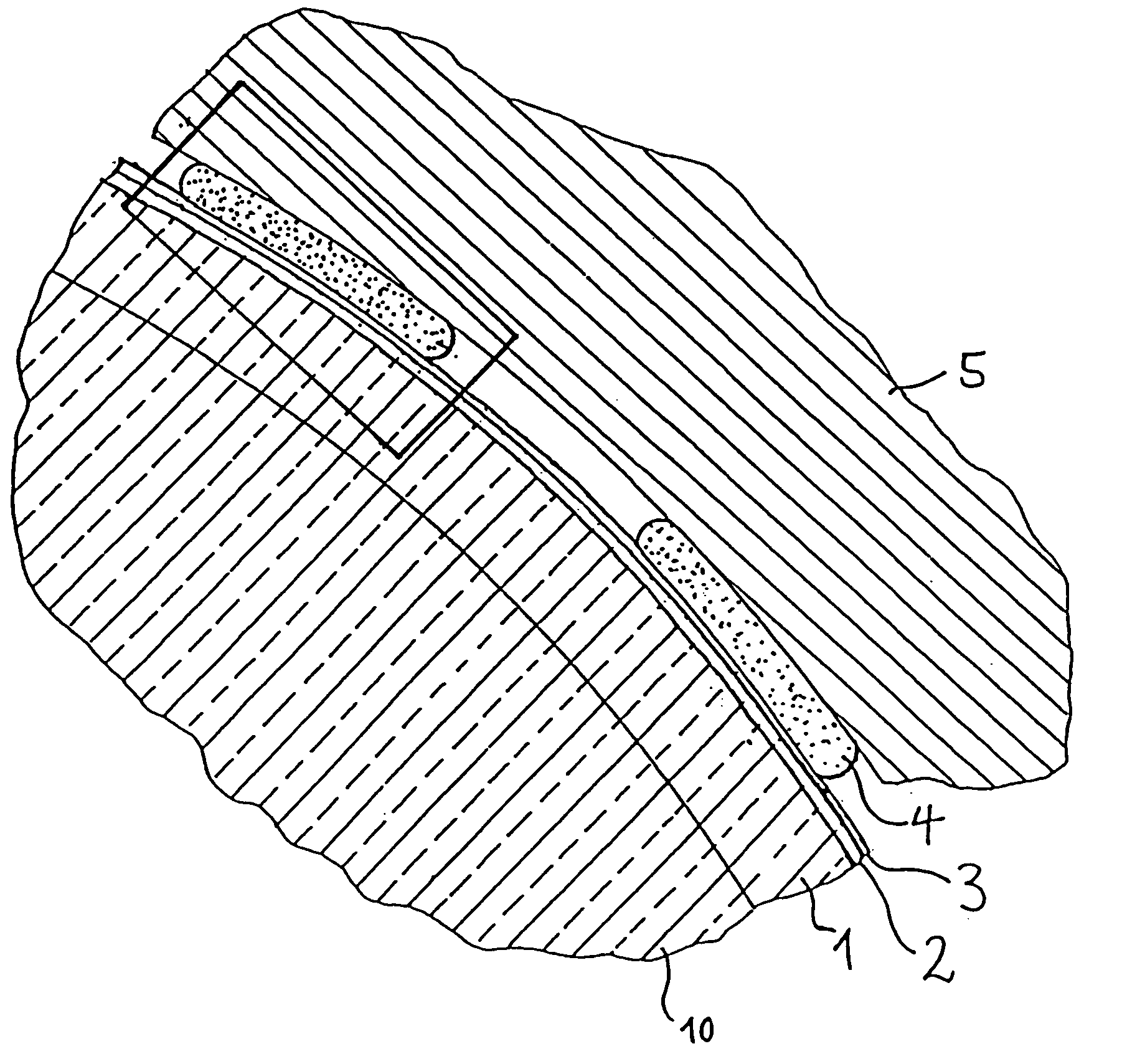
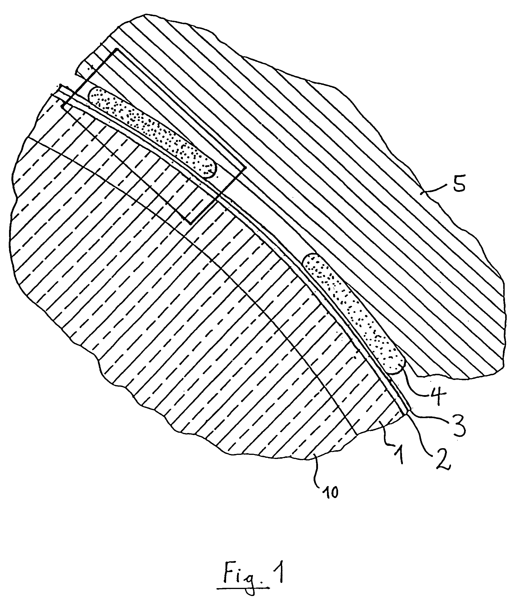
[0028] The assembly schematically shown in FIG. 1 has an optical component 1, namely a lens. In other embodiments, the optical component may be a flat plate, a prism, a Mangin mirror or a transmitting diffractive optical element. The optical component 1 includes a circular transmitting zone 10, within which the component 1 is capable of transmitting UV radiation from the VUV or DUV region, e.g. laser radiation at about 248 nm, 193 nm or 157 nm, essentially without absorption. Outside of the transmitting zone 10, on the edge of the transparent component 1, an adhesion-enhancing second layer 2 is applied, covering the edge of the component 1 continuously or as a distributed section. The adhesion-enhancing layer 2 is covered continuously by an adhesive-protecting first layer 3. The assembly additionally includes a holder (lens mount 5) made of metal. In other embodiments, the holder may be made of plastics or ceramic / glass-ceramic. The holder material is not transparent to ultraviolet ...


PUM


Abstract

An assembly includes a holder (5), an optical component (1) transmitting radiation in a first region of ultraviolet (UV) radiation adhered to the holder by an adhesive (4), the adhesive being hardenable by radiation of a second region of ultraviolet radiation, a first layer (3) disposed between the optical component and the adhesive, and a second layer (2) for enhancing adhesion between the optical component and the first layer. The first layer is capable of transmitting radiation of the second region of UV radiation and obstructing to a high degree transmission of UV radiation of the first region by at least one of absorption and reflection. The optical component has a transmitting zone and the first layer is located outside of the transmitting zone. The second layer for enhancing adhesion between the optical component and the first layer is disposed between the first layer and the optical component. The assembly can be used, for example, in an illumination system and/or a projection system of a microlithography projection apparatus.

Description

BACKGROUND OF THE INVENTION [0001] 1. Field of the Invention [0002] The invention relates to an assembly including a holder—in particular, a mount—and an optical component adhered to the holder by an adhesive, wherein the optical component is suitable for transmitting radiation in a first region of ultraviolet (UV) radiation, and wherein the adhesive is hardened by UV radiation in a second region of ultraviolet radiation, the adhesive being protected from radiation of the first region of ultraviolet radiation by an adhesive-protecting layer. [0003] 2. Description of the Related Art [0004] Japanese Patent Application JP 8-72300 provides an example of an assembly with an ultraviolet curable adhesive. Such assemblies form, among other things, mounted lenses and the like of illumination systems and projection systems for microlithography. [0005] Japanese Patent Application JP 11-014876 describes a protective member for shielding the surface of the adhesive of such an assembly from ultra...

Claims


Application Information

Patent Timeline
IPC IPC(8): G02B1/00
CPCG02B7/025G03F7/7095G03F7/70825
Inventor BRUYNOOGHE, STEPHANEULLMANN, JENS
Owner CARL ZEISS SMT GMBH
Why Eureka
Try Eureka