Device for separating, enriching and detecting ions

a technology for detecting devices and ions, applied in the field of enrichment and detection of chemicals, can solve the problems of easy to miss the contaminated part, the number of analyte cannot be absorbed, and the adsorption and desorption of analyte requires a relatively long time, so as to enhance the detection efficiency, increase the ion enrichment time, and maintain the spatial resolution of the device

Active Publication Date: 2011-09-15
SHIMADZU RES LAB SHANGHAI
View PDF8 Cites 24 Cited by
  • Summary
  • Abstract
  • Description
  • Claims
  • Application Information

AI Technical Summary

Benefits of technology

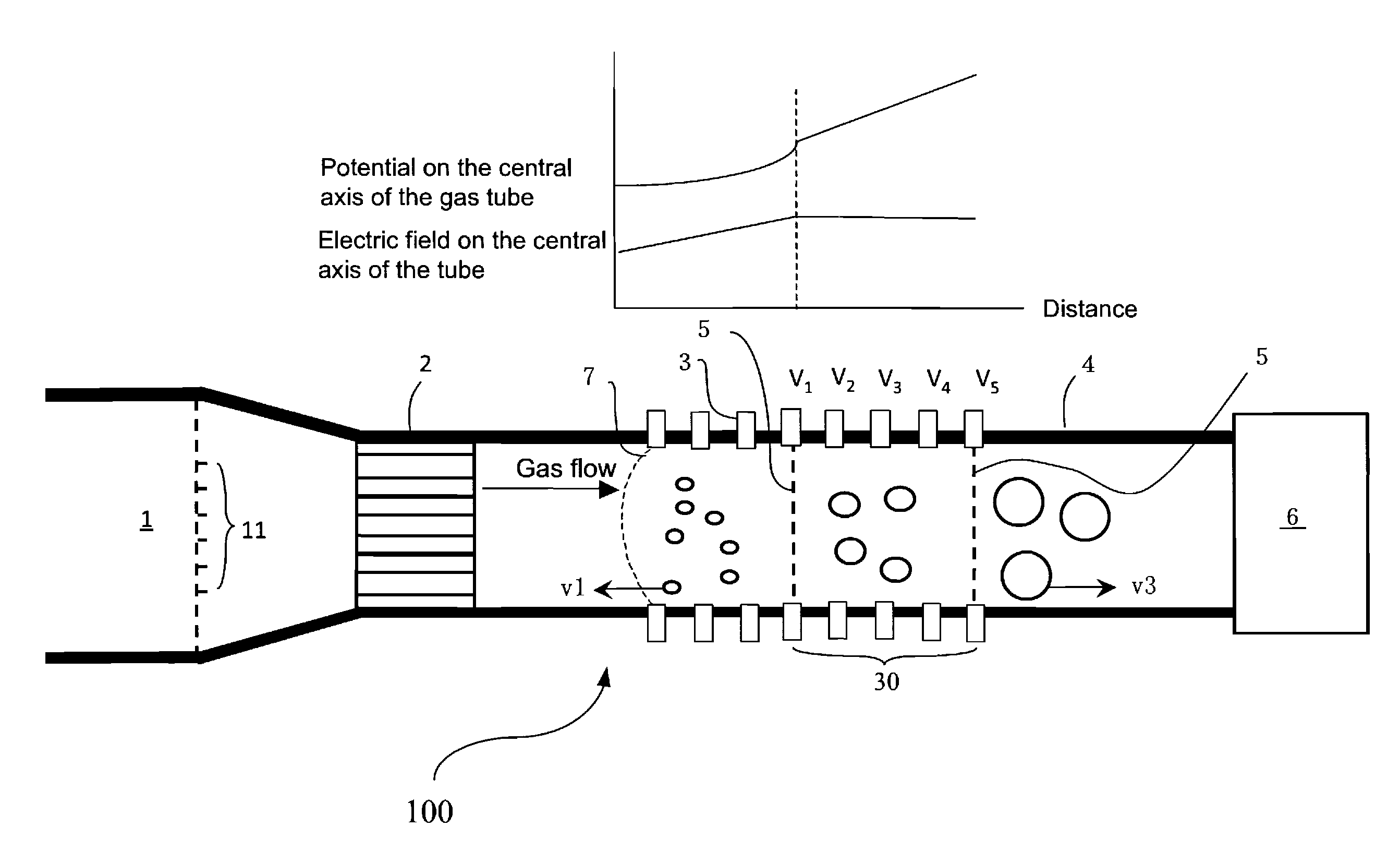
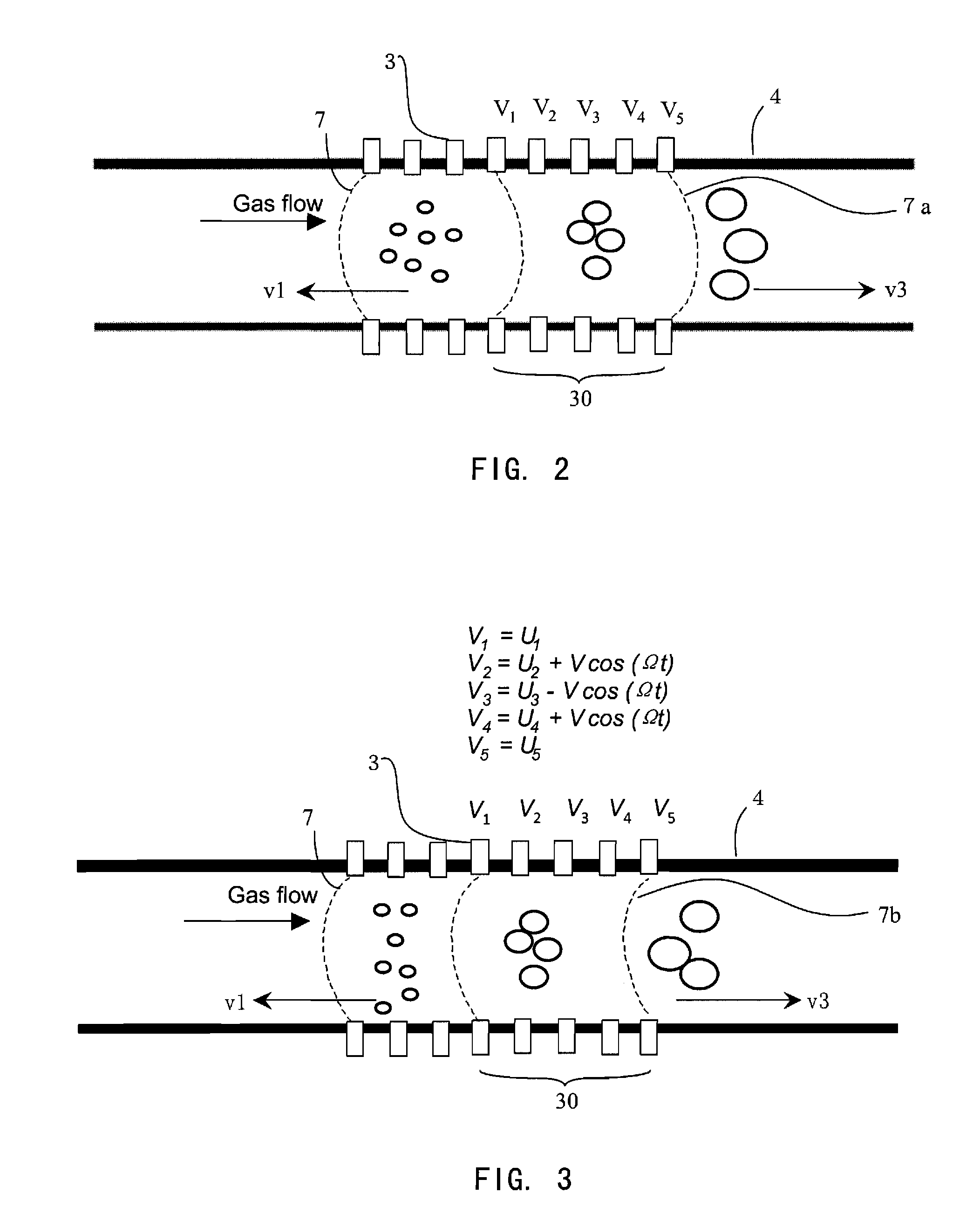
[0029]In the present invention, by increasing the radial electric field one can further increase the ion enrichment time. On the other hand, the invention provides the method for enriching different ions at different times or in multiple regions at the same time. Furthermore, since the axial electric field distribution along the gas tube can be changed by changing voltages applied on the different electrodes, the spacing between different enrichment regions can also adjusted, which makes it possible to mount multiple ion extraction channels in fixed positions along the gas tube. Since each ion trap in the ion trap array corresponds to an enrichment region, the ion groups in various regions can be extracted radially at the same time, and be captured and detected by the corresponding ion trap, which greatly enhance the detection efficiency while maintaining the spatial resolution of the device.

Problems solved by technology

However, the limitations of this method is the need to have someone perform the sample collection from targeted mater or persons, and a localized sampling can not cover all of the measured object, so easy to miss the contaminated part.
However, within this approach, there are still large number of analyte can not be absorbed and the adsorption and desorption requires a relatively long time.
However, such ion enrichment devices did not separate or select the ion to be enriched, therefore it is non-selective enrichment.
Above methods are neither meant to be working in high flow condition as the high flow velocity might cause instability of ion in the enrichment region, so the sample throughput is limited.
However, the purpose of the experiment in that time is to measure the speed ratio of two ions under the application of the electric field, so no ion enrichment is detected.
This method only improved the resolution of DMA, but no enrichment can be achieved since the retention time in the drifting tube is very limited as the result of existence of axial field component.
Similar to Loscertale and Tammet, this method didn't achieve the enrichment of the ion even though the balance of flow and electric field is satisfied, because again there exists the radial force.
However, the way relying on changes in diameter to change the gas axial velocity ignored the gas radial velocity changes, the radial velocity component of the ion causes rapid movement to the wall, so that the ion concentration becomes very difficult.
This gives an evidence of difficulty in the enrichment method proposed by Ichimura's patent.
However, this method can only be able to collect the ion group that is selected by one of the compensation voltage (CV) of the DMS.
Large amount of useful and informative ions will be lost.
Another limitation of this method is that ions concentrated in the tube are finally detected by removing them out of the tube in the axial direction, so the ions that have been already separated according to their mobility may be diffused again in the process of detection, thus the resolution of separation is deteriorated.
Also, the introduction of ions from the ion source should be suspended during the detection period, therefore reduces the operation efficiency.

Method used


Image

  • Device for separating, enriching and detecting ions
  • Device for separating, enriching and detecting ions
  • Device for separating, enriching and detecting ions

Examples


Embodiment Construction

[0040]This invention involves sample enrichment, separation, and detection after ionization in the gas phase. The invention is especially advantageous for detecting trace amount of substance such as explosives and illicit drugs concerned by public security department.

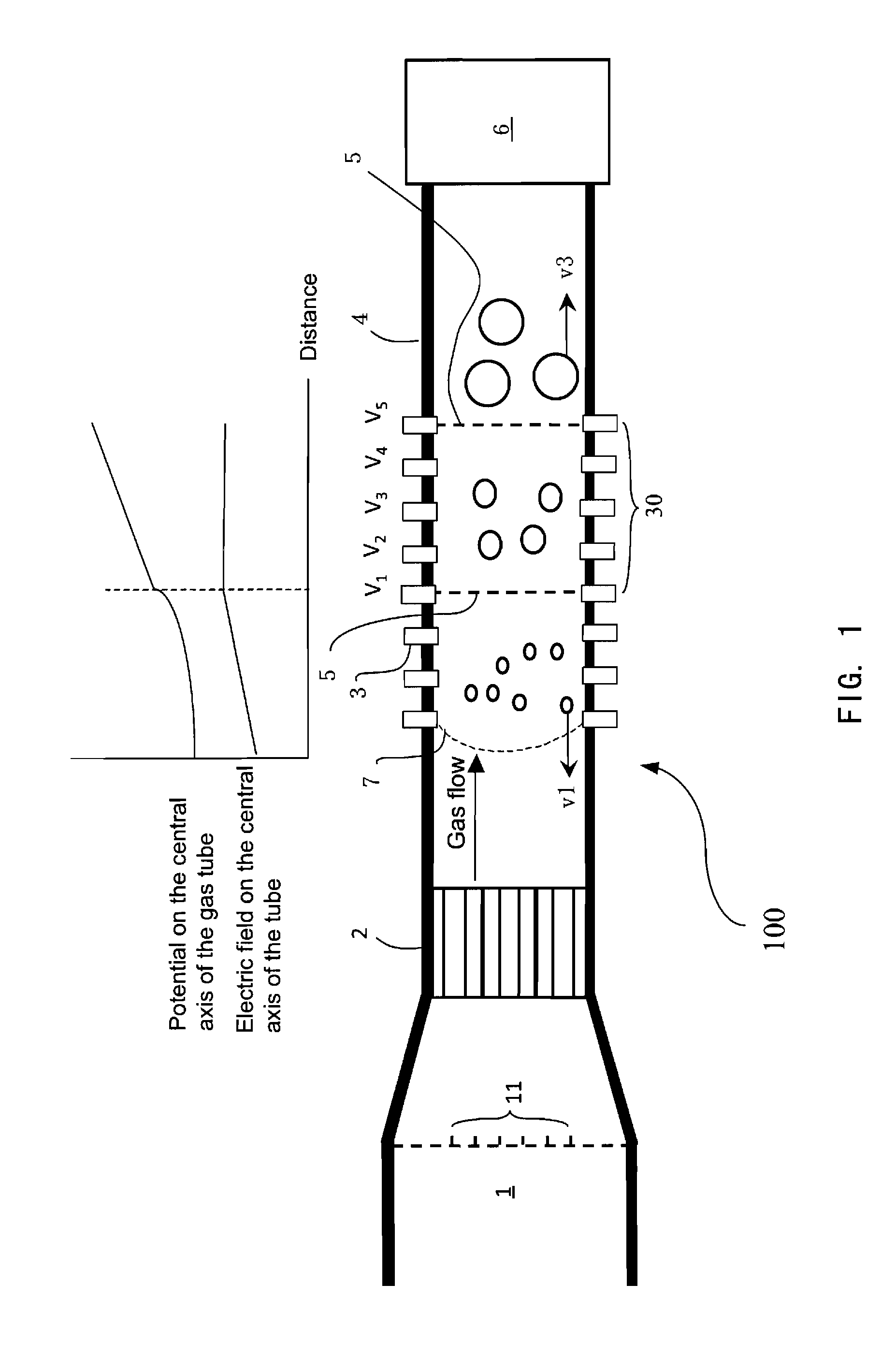
[0041]As shown in FIG. 1, the gas containing analytes enters the ion enrichment device from the left side of device 100 of the gas tube 4. The gas containing analytes will go through a continuous ion source before entering the gas tube 4. In order to rapidly ionize the trace amount of analyte in the gas flow, the ion source 1 can be an array of corona or glow discharge ion source with discharge needle array. Compared with the single needle discharge source used in normal ion source, the present design has better ionization efficiency with multiple discharge needles 11 located on different positions of the cross section of the gas tube 4. For such an ion source, one can change the polarity of the voltage applied on the n...


PUM


Abstract

A device for separating, enriching and detecting ions comprises: a gas tube, in which a carrier gas flows at a uniform rate; an ion source; multiple electrodes provided in the gas tube and applied with electric voltages respectively, so that at least an electric field is produced along the axis of the gas tube; an ion detector; and an ion extraction channel, by which specific enriched ions will be guided across the side wall of the gas tube toward the ion detector and be analyzed. The device enriches ions utilizing the following characteristic: compound ions with specific ion mobility maintain a dynamic balance for a period of time in a flow field under the combination of a carrier gas and a suitable electrical field against the direction of the carrier gas. Simultaneously, multiple compound particles with different ion motilities can be separated and enriched at positions with different electrical field intensities in a flow field in the same manner. The device also comprises synchronously export latitudinally enriched ions at different positions in a flow field, and performs later mass analysis using a mass spectrometer.

Description

FIELD OF THE INVENTION[0001]The invention relates to enrichment and detection of chemicals, and more particularly, to a device for separating, enriching and detecting ions.BACKGROUND OF THE INVENTION[0002]Fast, accurate and sensitive detection equipment is highly demanded in dealing with the increasing problem of worldwide smuggling, drug trafficking and acting of terrorism. At present, the ion mobility spectrometer with its lightweight, fast, and sensitive performance has been widely used in public security checking points such as in the airport and sport stadium. Ion mobility spectrometry is a relatively new gas separation and detection methods. Different from the gas chromatography, the compounds to be separated and detected in the ion mobility spectrometer must be ionized, and then under the effect of the electric field in accordance with the molecular size of the ion to be separated.[0003]In principle, there are two categories of ion mobility spectrometers may be used in variou...

Claims


Application Information

Patent Timeline
Patent Type & Authority Applications(United States)
IPC IPC(8): H01J49/22
CPCG01N27/622G01N15/0266G01N27/623
Inventor SUN, WENJIANDING, LI
Owner SHIMADZU RES LAB SHANGHAI
Why Eureka
Try Eureka