Tamping and trowelling device for building concrete laying

A concrete and construction technology, applied in the processing of building materials, construction, soil protection, etc., can solve the problems of machine tamping and leveling, waste of manpower, etc., and achieve the effect of saving manpower and material resources, high work efficiency, and smooth ground.

Inactive Publication Date: 2020-09-08
栾勇
View PDF13 Cites 7 Cited by
  • Summary
  • Abstract
  • Description
  • Claims
  • Application Information

AI Technical Summary

Problems solved by technology

[0004] The existing equipment only realizes the function of compaction or smoothing alone, and the same machine cannot perform compaction and smoothing at the same time, which often requires secondary engineering and wastes manpower

Method used


Image

  • Tamping and trowelling device for building concrete laying
  • Tamping and trowelling device for building concrete laying
  • Tamping and trowelling device for building concrete laying

Examples


Embodiment 1

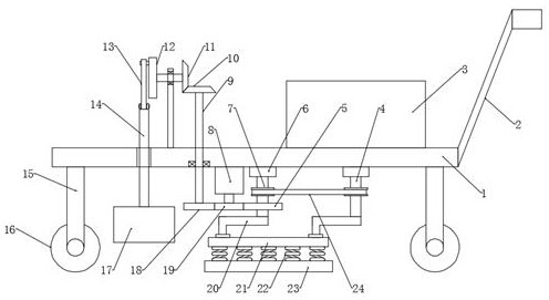
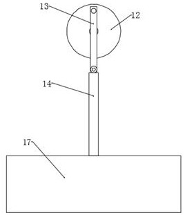
[0024] see Figure 1~2 , in an embodiment of the present invention, a tamping and leveling device for building concrete laying, comprising a base plate 1 and a tamping block 17, support legs 15 are fixed on the four corners of the bottom of the base plate 1, and the bottom ends of the support legs 15 are installed with The roller 16, the roller 16 is a self-locking roller, the right end of the base plate 1 is fixed with the hand frame 2, the tool box 3 is installed on the right side of the upper surface of the base plate 1, the motor 8 is installed in the middle of the bottom of the base plate 1, and the end of the output shaft of the motor 8 is installed There is a first gear 19, the left side of the first gear 19 is provided with a second gear 18, the second gear 18 meshes with the first gear 19, the second gear 18 is installed on the bottom end of the first rotating shaft 9, and the other end of the first rotating shaft 9 runs through The base plate 1 extends to the top of ...

Embodiment 2

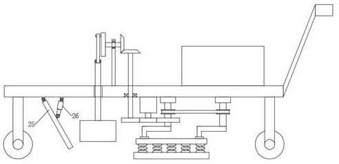
[0026] see image 3 , The difference between this embodiment and Embodiment 1 is that it also includes a tiling mechanism, and the tiling mechanism includes a tiling plate 25 and an electric push rod 26. 1 The lower surface is located on one side of the tiled board 25, and an electric push rod 26 is hingedly installed. The end of the telescopic rod of the electric push rod 26 is hinged with the side wall of the tiled board 25. On the ground, by controlling the stretching or shortening of the telescopic rod of the electric push rod 26, the distance between the bottom end of the tiled board 25 and the ground is adjusted, so that the concrete can be tiled with different thicknesses according to the operation requirements to meet the needs of different situations .

[0027] The working principle of the present invention is: when the present invention is in use, push the device to the working position, then start the motor 8, the motor 8 drives the first gear 19 to rotate, the fir...


PUM


Abstract

The invention discloses a tamping and trowelling device for building concrete laying. The tamping and trowelling device comprises a bottom plate, a tamping block, a motor, a first gear, a second gear,a first rotating shaft, a first bevel gear, a second bevel gear, a disc, a connecting rod, a movable rod, a tamping block, a third gear, a second rotating shaft, a third rotating shaft, an L-shaped rod and a pressing plate. The tamping and trowelling device is provided with a motor, a first gear, a second gear, a first rotating shaft, a first bevel gear, a second bevel gear, a disc, a movable rodand a tamping block. The tamping block is driven to move up and down, continuous tamping on the road surface is realized, tamping speed is fast, efficiency is high; the third gear, the second rotating shaft, the third rotating shaft, the L-shaped rod, a mounting plate and a pressing plate are adopted for extruding and trowelling of the ground, the working range is large, the efficiency is high, tamping and trowelling functions are achieved at the same time through a motor, the road surface is processed to be smooth, working efficiency is high, and both manpower and material resources are saved.

Description

technical field [0001] The invention relates to the technical field of construction equipment, in particular to a compacting and smoothing device for laying construction concrete. Background technique [0002] Construction engineering refers to the engineering entity formed through the construction of various housing buildings and their ancillary facilities and the installation activities of supporting lines, pipelines and equipment. Among them, "housing construction" refers to projects that have roofs, beams, walls, foundations, and can form internal spaces to meet people's needs for production, living, learning, and public activities. [0003] In construction engineering operations, such as pavement laying, ground concrete laying, foundation concrete laying, etc., various machines are required. Generally, after laying concrete manually, it is compacted by a tamping machine, and finally once again Do smoothing work. [0004] Existing equipment only realizes the function o...

Claims


Application Information

Patent Timeline
IPC IPC(8): E01C19/40E02D3/068E04G21/06E04G21/10
CPCE01C19/405E02D3/068E04G21/066E04G21/10
Inventor 栾勇
Owner 栾勇
Why Eureka
Try Eureka