
Dustproof surrounding-air-inlet Bunsen burner

A Bunsen burner and air intake technology, which is applied in the field of Bunsen burners, can solve the problems of inability to adjust the air intake amount, inability to adjust the length of the combustion flame, and the combustion flame being easily blown by the wind.

Pending Publication Date: 2020-09-08
苏州忻智铭传感电子科技有限公司
View PDF0 Cites 0 Cited by
  • Summary
  • Abstract
  • Description
  • Claims
  • Application Information

AI Technical Summary

Problems solved by technology

[0003] However, in the actual use of ordinary Bunsen burners, there are the following problems: 1. With various combustion gases such as propane, acetylene, methane, butane, etc., being used as fuel for ordinary Bunsen burners, compared with the original gas , when different combustion gases are fully combusted, their mixing ratios with air are different, and an air flow regulating device that can adjust the air intake volume is required. Ordinary Bunsen burners can only adjust the gas intake volume, but cannot adjust the air intake volume. Gas capacity; 2. Sometimes it is necessary to adjust the length of the burning flame at the base of the Bunsen burner, and the ordinary Bunsen burner cannot adjust the length of the burning flame; 3. When using an ordinary Bunsen burner, no matter which fuel is used, it is sometimes easy to burn during use. There is smoke and dust, especially at the lamp head; at the same time, the burning flame at the lamp head of the ordinary Bunsen burner cannot be protected from wind, so that the burning flame is easily blown by the wind, and the area that actually needs to be heated is shifted

Method used


Image

  • Dustproof surrounding-air-inlet Bunsen burner
  • Dustproof surrounding-air-inlet Bunsen burner
  • Dustproof surrounding-air-inlet Bunsen burner

Examples


Embodiment Construction

[0018] The following will clearly and completely describe the technical solutions in the embodiments of the present invention with reference to the accompanying drawings in the embodiments of the present invention. Obviously, the described embodiments are only some, not all, embodiments of the present invention. Based on the embodiments of the present invention, all other embodiments obtained by persons of ordinary skill in the art without making creative efforts belong to the protection scope of the invention.

[0019] The present invention will be described in further detail below in conjunction with examples and specific implementation methods.

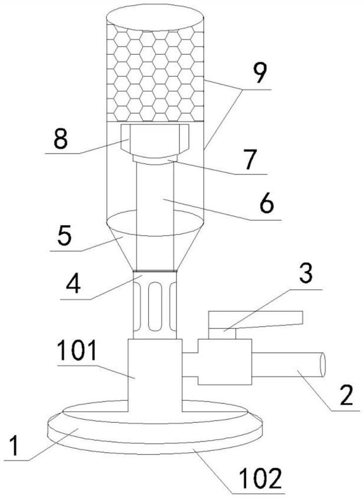
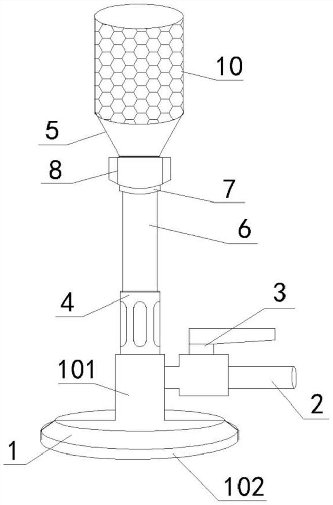
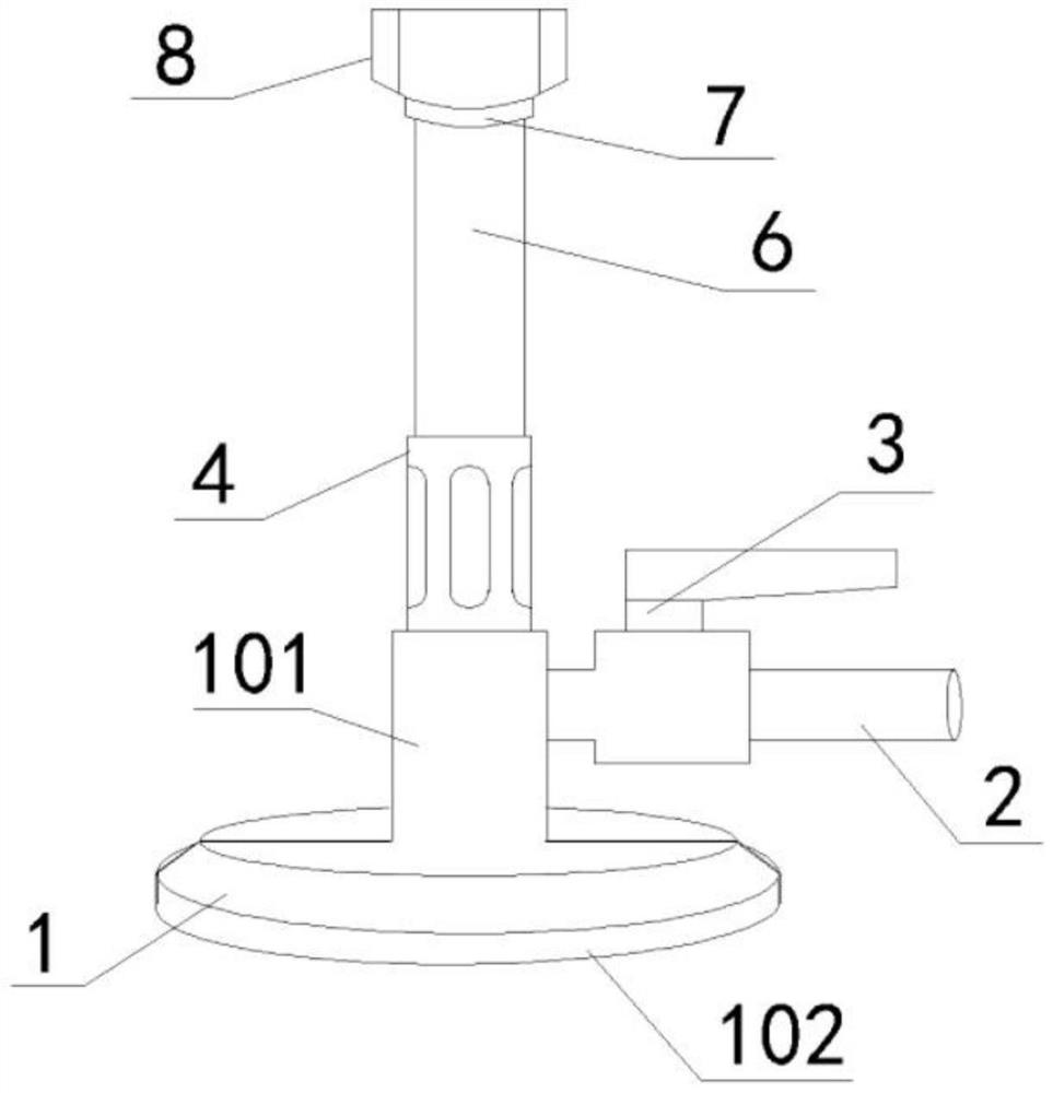
[0020] See the accompanying drawings: a dust-proof surrounding air-intake Bunsen burner, which is characterized in that it includes a lamp holder 1, a gas input pipe 2, a valve 3, an air flow adjustment sleeve 4, a lamp tube 6, an adjustable lamp holder 8, and an adjustment nut 7 , funnel bracket 5 and dust cover (9 and 10), there ...


PUM


Abstract

The invention discloses a dustproof surrounding-air-inlet Bunsen burner. The dustproof surrounding-air-inlet Bunsen burner is characterized by comprising a lamp holder, a fuel gas input pipe, a valve,an air flow rate adjusting sleeve, a modulator tube, an adjustable lamp cap, an adjustable nut, a hopper saddle and a dustproof cover. The fuel gas input pipe is screwed into the side face of the upper side of the lamp holder. The valve is installed on the fuel gas input pipe. The air flow rate adjusting sleeve is screwed into the lower portion of the modulator tube. The bottom of the adjustablelamp cap and the bottom of the adjustable nut are both screwed into the upper portion of the modulator tube. A through hole is formed in the middle of the hopper saddle. The hopper saddle sleeves theouter side of the modulator tube through the through hole in the middle. The dustproof cover is installed on the upper face of the hopper saddle. By means of the dustproof surrounding-air-inlet Bunsenburner, the air inlet amount can be adjusted, it is ensured that air and fuel gas are sufficiently mixed in the modulator tube, the lamp cap can be adjusted according to actual demands, the length ofcombusting flames is adjusted, the dustproof cover has windproof, dustproof and high-temperature resistant performance, and the dustproof surrounding-air-inlet Bunsen burner is high in stability, safe, environmentally friendly and suitable for use as a high-temperature heating tool in experiments or other product production processes.

Description

technical field [0001] The invention relates to the field of Bunsen burners, in particular to a dust-proof surrounding wind-intake Bunsen burner. Background technique [0002] The Bunsen burner is a medium-high temperature heating tool commonly used by the people. With the development of modern technology, the combustion gas of the Bunsen burner has gradually expanded from the original gas to propane, acetylene, methane, butane, etc., and has gradually separated from the gas source. Lamp fuel restrictions. The scope of use of the Bunsen burner has been limited to the original laboratory, and gradually expanded to the laboratory and some manufacturing enterprises. [0003] However, in the actual use of ordinary Bunsen burners, there are the following problems: 1. With various combustion gases such as propane, acetylene, methane, butane, etc., being used as fuel for ordinary Bunsen burners, compared with the original gas , when different combustion gases are fully combusted,...

Claims


Application Information

Patent Timeline
IPC IPC(8): F23D14/08F23D14/46F23D14/62
CPCF23D14/08F23D14/46F23D14/62
Inventor 孟超王守明胡勤
Owner 苏州忻智铭传感电子科技有限公司
Learn More