
A paint spraying device for a coat rack rod

A coat rack and sliding rod technology, applied in the direction of spraying devices, etc., can solve the problems of manpower consumption, low work efficiency, cumbersome operation process, etc.

Active Publication Date: 2021-04-20
东营宏基混凝土有限公司
View PDF6 Cites 0 Cited by
  • Summary
  • Abstract
  • Description
  • Claims
  • Application Information

AI Technical Summary

Problems solved by technology

[0006] In order to overcome the cumbersome operation process and low work efficiency of the above method, the present invention needs manual hand-held painting equipment to spray paint during operation, which is relatively labor-intensive. The technical problem to be solved by the present invention is to provide a simple operation that can Coat rack rod painting device that improves work efficiency and saves manpower during operation

Method used


Image

  • A paint spraying device for a coat rack rod
  • A paint spraying device for a coat rack rod
  • A paint spraying device for a coat rack rod

Examples


Embodiment 1

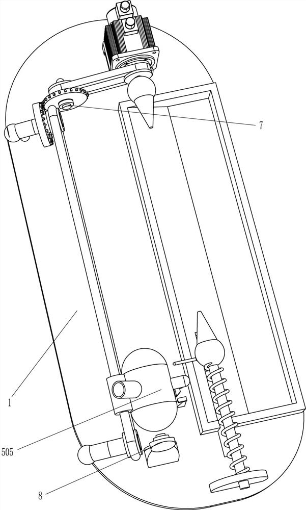
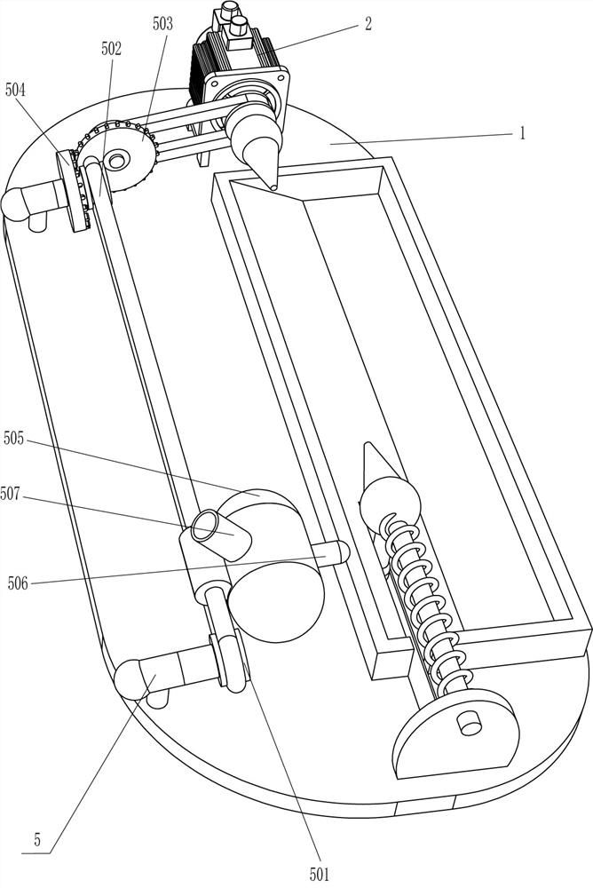
[0025] A painting device for a coat rack rod such as Figure 1-2 As shown, it includes a base 1, a motor 2 and a material guide frame 3, the motor 2 is installed on the rear side of the top of the base 1, the material guide frame 3 is connected to the top right side of the base 1, and a clamping mechanism 4 and a painting mechanism 5 are also included. The base 1 is provided with a clamping mechanism 4 and a painting mechanism 5 .

[0026] The clamping mechanism 4 includes a card seat 401, a first slide bar 402, a pressure spring 403 and a fixing seat 404. The front side of the top of the base 1 is slidably connected to a first slide bar 402, and the rear end of the first slide bar 402 is connected to a card seat. 401 , a pressure spring 403 is connected between the first slide bar 402 and the base 1 , and a fixed seat 404 is connected to the output shaft of the motor 2 , and the fixed seat 404 cooperates with the card seat 401 .

[0027] The painting mechanism 5 includes a s...

Embodiment 2

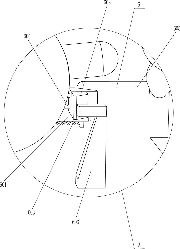
[0030] On the basis of Example 1, such as Figure 3-4 As shown, a discharge mechanism 6 is also included. The discharge mechanism 6 includes a horizontal plate 601, a wedge block 602, an elastic member 603, a second slide bar 604, a pull bar 605 and an oblique bar 606. The right side of the barrel 505 is connected with A horizontal plate 601, a wedge block 602 is slidably connected to the horizontal plate 601, an elastic member 603 is connected between the wedge block 602 and the horizontal plate 601, a second slide bar 604 is connected to the bucket 505, the second slide bar 604 and the wedge The block 602 is slidingly fitted, and the first slide bar 402 is connected with a pulling rod 605, which will contact the wedge-shaped block 602, and the front side of the top of the base 1 is connected with a slanting rod 606, which will contact the wedge-shaped block 602.

[0031] When the bucket 505 moves forward and backward, it drives all the devices on it to move forward and backw...


PUM


Abstract

The invention relates to a painting device, in particular to a painting device for a coat rack rod. The technical problem to be solved by the present invention is how to design a paint spraying device for a coat rack rod that is simple to operate, can improve work efficiency, and can save manpower during operation. The present invention provides such a paint spraying device for a coat rack rod, comprising: a base, a motor is installed on one side of the top; a material guide frame, which is connected to the top of the base; a clamping mechanism, which is arranged on the base, The mechanism is used for clamping the rod of the coat rack; the paint spraying mechanism is arranged on the base, and the paint spraying mechanism is used for spraying paint on the rod of the coat rack. In the present invention, the clamping mechanism and the painting mechanism cooperate to spray paint on the coat rack rod, so as to achieve the effect of spraying paint on the coat rack rod.

Description

technical field [0001] The invention relates to a painting device, in particular to a painting device for a coat rack rod. Background technique [0002] In real life, wooden coat racks are used more than metal ones, because wooden coat racks are relatively heavier than metal ones, which will play a role in balancing support. Use and structure: Furniture used to hang clothes in home life is generally divided into bases, poles and hooks. After the coat rack is made, it is usually necessary to spray paint the coat rack rod to make the coat rack rod more beautiful. [0003] At present, the way of painting the coat rack rod is usually to manually fix the coat rack rod on the rotating device, and then start the handheld paint spraying device to spray paint on the coat rack rod. The operation process of the above method is cumbersome and the work The efficiency is low, and manual hand-held painting equipment is required for painting during operation, which is more labor-intensive...

Claims


Application Information

Patent Timeline
Patent Type & Authority Patents(China)
IPC IPC(8): B05B13/02B05B13/04
CPCB05B13/0221B05B13/0228B05B13/041
Inventor 王地长
Owner 东营宏基混凝土有限公司
Learn More