A fastening mechanism for lifting and lowering silicon carbide glass steel pipes

A technology of glass steel pipe and fastening mechanism, which is applied in the directions of load hanging components, balance weight, transportation and packaging, etc., can solve the problems of time-consuming and laborious, inability to clamp silicon carbide glass steel pipe, and shaking of silicon carbide glass steel pipe and hoisting device. , to achieve the effect of increasing friction and uniform force

Active Publication Date: 2021-04-23
亳州专海智能科技有限公司
View PDF5 Cites 0 Cited by
  • Summary
  • Abstract
  • Description
  • Claims
  • Application Information

AI Technical Summary

Problems solved by technology

[0002] After the production and processing of silicon carbide glass steel pipes, it is necessary to use the lifting device to lift the silicon carbide glass steel pipes to a high place on the storage rack and place them in an orderly manner. The existing lifting device for silicon carbide glass steel pipes cannot move larger silicon carbide The glass steel pipe is clamped, and the silicon carbide glass steel pipe shakes between the lifting device, so it often occurs that the silicon carbide glass steel pipe is dropped and damaged during the lifting and handling process, and it is time-consuming and laborious to disassemble the silicon carbide glass steel pipe from the lifting device, so Need a kind of device badly to solve the above problems

Method used


Image

  • A fastening mechanism for lifting and lowering silicon carbide glass steel pipes
  • A fastening mechanism for lifting and lowering silicon carbide glass steel pipes
  • A fastening mechanism for lifting and lowering silicon carbide glass steel pipes

Examples


Embodiment Construction

[0021] The following will clearly and completely describe the technical solutions in the embodiments of the present invention with reference to the accompanying drawings in the embodiments of the present invention. Obviously, the described embodiments are only some, not all, embodiments of the present invention. Based on the embodiments of the present invention, all other embodiments obtained by persons of ordinary skill in the art without making creative efforts belong to the protection scope of the present invention.

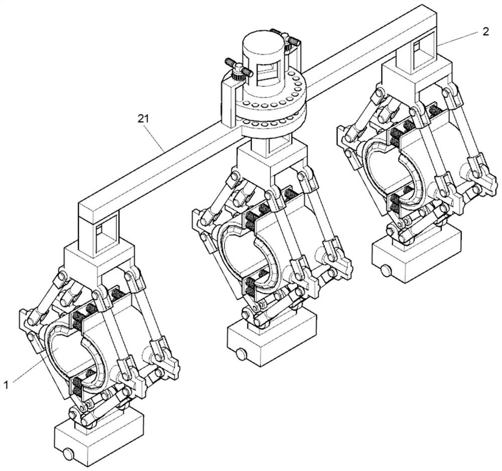
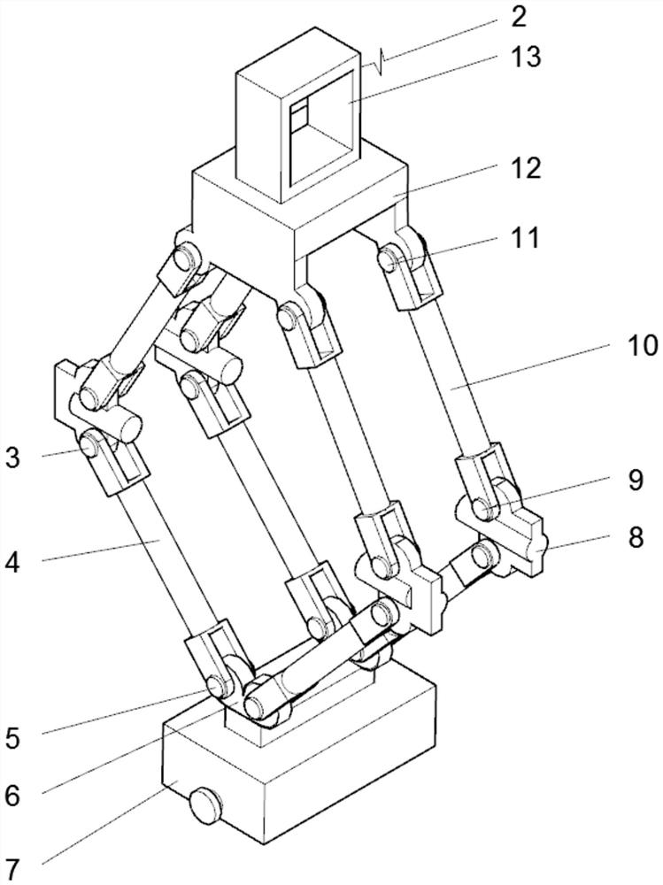
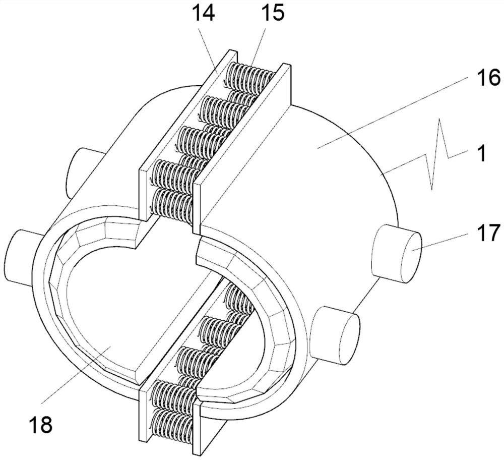
[0022] see Figure 1-6, an embodiment provided by the present invention: a fastening mechanism for lifting and lowering silicon carbide glass steel pipes, including a clamping mechanism 2, the clamping mechanism 2 is provided with three and uniform parts, and a counterweight tank is installed at the bottom of the clamping mechanism 2 7. The upper end surface of the counterweight tank 7 is symmetrically welded with a connecting block 6, and both ends of the con...


PUM


Abstract

The invention discloses a fastening mechanism for lifting and lowering a silicon carbide glass steel pipe, comprising a clamping mechanism, the clamping mechanism is provided with three uniform parts, a counterweight tank is installed at the bottom of the clamping mechanism, and the counterweight The upper end surface of the tank is symmetrically welded with a connecting block, and the two ends of the connecting block are rotatably installed with a second plug-in shaft, and both ends of the second plug-in shaft are connected with a first connecting rod, and the first connecting rod The upper end of the connecting rod is fixedly connected with the first plug-in shaft, and the middle part of the first plug-in shaft is equipped with an adjustment plate, and the first plug-in shaft is rotatably inserted in the bottom end of the adjustment plate, and the adjustment plate The upper end of the third plug-in shaft is rotatably engaged with a third plug-in shaft, and the upper ends of the third plug-in shaft are fixedly connected with second connecting rods. During the use of the present invention, the large silicon carbide glass steel pipes that need to be lifted and transported to the placement rack can be firmly clamped and lifted, and it is convenient to place the silicon carbide glass steel pipes inside the device, and it is also convenient for the silicon carbide glass steel pipes to be placed in the device. remove.

Description

technical field [0001] The invention relates to the technical field of production and processing of silicon carbide glass steel pipes, in particular to a fastening mechanism for lifting silicon carbide glass steel pipes. Background technique [0002] After the production and processing of silicon carbide glass steel pipes, it is necessary to use the lifting device to lift the silicon carbide glass steel pipes to a high place on the storage rack and stack them in an orderly manner. The existing lifting device for silicon carbide glass steel pipes cannot move larger silicon carbide The glass steel pipe is clamped, and the silicon carbide glass steel pipe shakes between the lifting device, so it often occurs that the silicon carbide glass steel pipe is dropped and damaged during the lifting and handling process, and it is time-consuming and laborious to disassemble the silicon carbide glass steel pipe from the lifting device, so A kind of device is urgently needed to solve the ...

Claims


Application Information

Patent Timeline
Patent Type & Authority Patents(China)
IPC IPC(8): B66C1/42B66C13/08F16F15/28
CPCB66C1/422B66C13/08
Inventor 谢春香
Owner 亳州专海智能科技有限公司
Why Eureka
Try Eureka