Municipal parking shed and mounting process thereof

An installation process and parking shed technology, which is applied in the direction of parking buildings, roofs, building components, etc., can solve the problems of drivers’ lack of feedback, rubbing, poor driving skills, etc., and achieve convenient installation and strong wind resistance Effect

Active Publication Date: 2020-09-11
ZHEJIANG DINGXING CONSTR
View PDF9 Cites 3 Cited by
  • Summary
  • Abstract
  • Description
  • Claims
  • Application Information

AI Technical Summary

Problems solved by technology

[0004] The above-mentioned existing technical solutions have the following defects: the existing municipal parking shed can be used for a large number of cars to be parked side by side. , mostly due to the lack of feedback to the driver when the vehicles are too close together

Method used


Image

  • Municipal parking shed and mounting process thereof
  • Municipal parking shed and mounting process thereof
  • Municipal parking shed and mounting process thereof

Examples


Embodiment 1

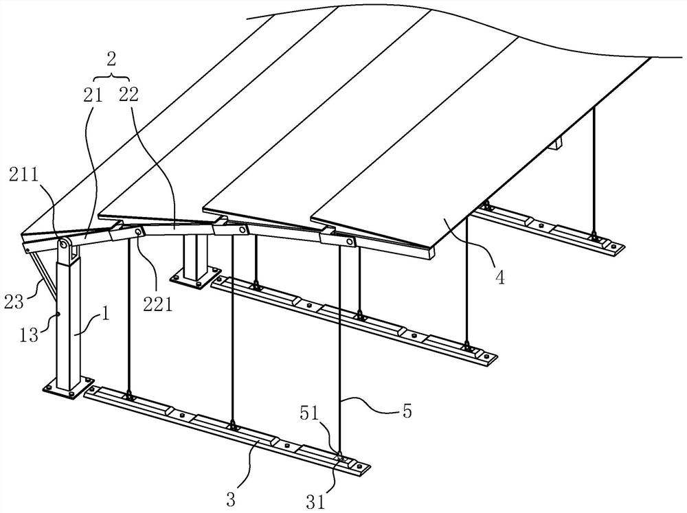
[0042] refer to figure 1 with figure 2 , is a municipal parking shed disclosed by the present invention, comprising a plurality of support columns 1, skeletons 2, and partition strips 3 arranged side by side. 3 is located below the skeleton 2, and the parking spaces are formed between 3 adjacent partition bars.

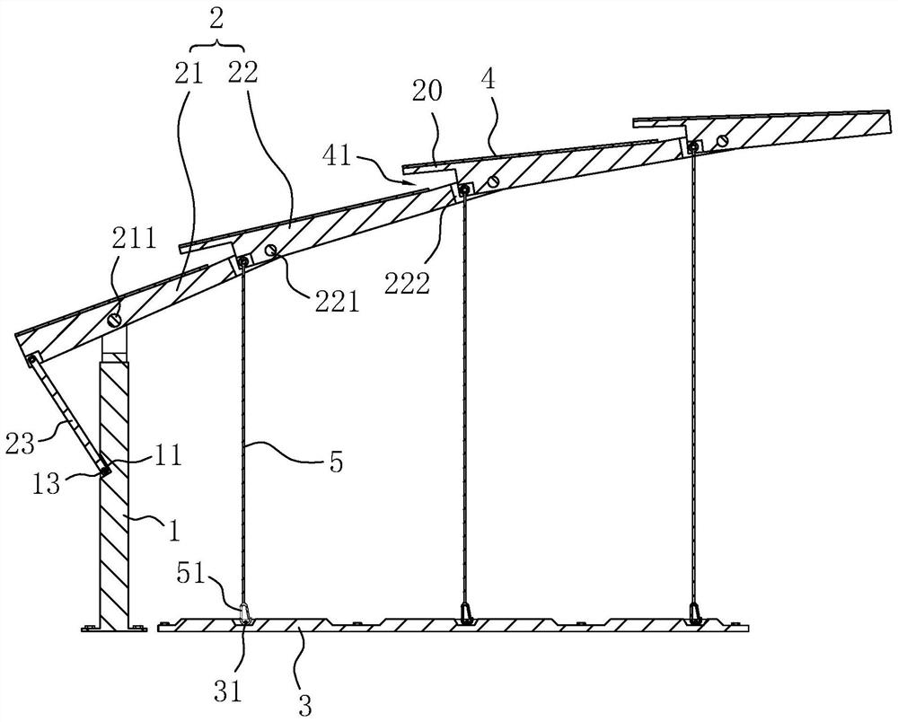
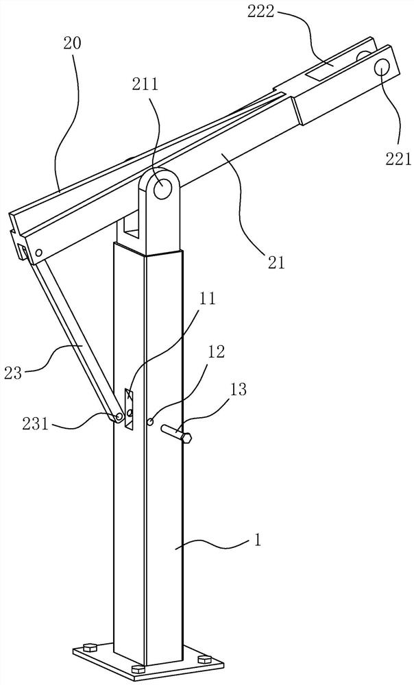
[0043] The support column 1 is fixed on the ground by anchor bolts. The framework 2 includes a main frame 21 connected to the support column 1 and a plurality of sub-frames 22 connected to the main frame 21 , wherein the main frame 21 establishes a connection between the support column 1 and the sub-frames 22 . The main frame 21 and the support column 1 are hinged through the hinge shaft 2 211 between the two. The axis of the hinge shaft 211 is along the arrangement direction of the support column 1, that is, the arrangement direction of the parking spaces. middle part.

[0044] refer to figure 2 with image 3 , the main frame 21 and the support column 1 are c...

Embodiment 2

[0054] An installation process of a municipal parking shed, comprising the following steps:

[0055] Support column 1, main frame 21, sub-frame 22 have been pre-assembled. Under the gravity of sub-frame 22, main frame 21 and sub-frame 22 are located in a drooping state close to support column 1, which is convenient for transportation and handling.

[0056] Step S1: Install the support column 1 and the partition bar 3 on the ground. During specific implementation, the support column 1 is put down on the ground earlier, then the ceiling 4 is installed on the main frame 21 and the subframe 22, and the support column 1 is erected after the ceiling 4 is installed, and the support column 1 is fixedly installed on the ground.

[0057] Step S2: Pull the fixing rod 23 to rotate the main frame 21 to a state extending horizontally, and then fix the fixing rod 23 to the support column 1 . The fixing rod 23 is fixed by the fixing slot 11 and the latch 13 .

[0058] Step S3: pull the pull...


PUM


Abstract

The invention discloses a municipal parking shed and a mounting process thereof, and relates to the technical field of municipal engineering. According to the technical scheme, the municipal parking shed comprises multiple supporting columns which are arranged side by side and frameworks, a ceiling is mounted between the adjacent frameworks, partition strips which are fixed to the ground are further included, parking space is formed between the adjacent partition strips, each framework comprises a main frame and multiple auxiliary frames, the adjacent auxiliary frames are in hinged connectionthrough first hinge shafts, the first hinge shafts are located on the near ends, towards the main frames, of the auxiliary frames, the auxiliary frames are connected with pull ropes, one ends of the pull ropes are connected to the ends, towards the main frames, of the auxiliary frames, and the other ends of the pull ropes are connected to the partition strips. When vehicles rub the pull ropes, thepull ropes can generate deforming to enable the auxiliary frames and the ceiling to generate deforming, sounds can be sent out while deforming is achieved, visual and hearing changes can be fed backto a driver, the driver can be promoted to change the behavior, the possibility of rubbing other vehicles can be reduced, the wind resistance capacity of the ceiling is high, rainwater is not prone todropping to the parking space downwards, and the parking shed can be conveniently mounted.

Description

technical field [0001] The invention relates to the technical field of municipal engineering, in particular to a municipal parking shed and an installation process thereof. Background technique [0002] The parking shed is a building structure used for parking in municipal construction. The parking shed can shield the vehicle from rain, snow and falling objects, and play a role in protecting the vehicle. [0003] The Chinese utility model patent with the existing authorized notification number CN207063612U discloses an environmentally friendly and energy-saving parking awning, which includes a canopy, LED lights, support columns, and a steel frame. There are four support columns, and the upper ends of the support columns are welded to the steel frame. A support plate is welded between the support column and the steel frame, and a canopy is arranged between the steel frame. [0004] The above-mentioned existing technical solutions have the following defects: the existing mun...

Claims


Application Information

Patent Timeline
Patent Type & Authority Applications(China)
IPC IPC(8): E04H6/10E04H6/42E04B7/10E04B7/16E04B7/18
CPCE04B7/102E04B7/16E04B7/18E04H6/10E04H6/42
Inventor 郭琳君
Owner ZHEJIANG DINGXING CONSTR
Why Eureka
Try Eureka