
Microactuator, head suspension assembly and disk device

A micro-driver and connection pad technology, which is applied in the configuration of the head, the installation of the arm parts, the configuration/installation of the recording head, etc., can solve the problem of increased displacement of the piezoelectric element, increased gap between electrodes, electrode short circuit, etc. question

Inactive Publication Date: 2020-09-11
KK TOSHIBA +1
View PDF4 Cites 0 Cited by
  • Summary
  • Abstract
  • Description
  • Claims
  • Application Information

AI Technical Summary

Problems solved by technology

However, in this case, since the electrodes are close to each other, there is a possibility that the two electrodes may be short-circuited by the conductive adhesive material when bonding to the conductive pad.
In order to prevent this, it is necessary to increase the gap between the electrodes, which will hinder the increase in the displacement of the piezoelectric element.

Method used


Image

  • Microactuator, head suspension assembly and disk device
  • Microactuator, head suspension assembly and disk device
  • Microactuator, head suspension assembly and disk device

Examples


Embodiment approach

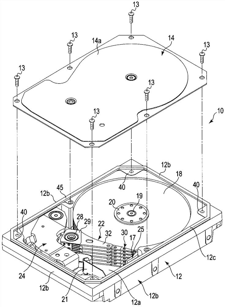
[0029] As a disk device, a hard disk drive (HDD) according to the embodiment will be described in detail.

[0030] figure 1 It is an exploded perspective view of the HDD of the embodiment shown with the cover removed. As shown in the figure, the HDD includes a rectangular housing 10 . The housing 10 has a rectangular box-shaped base 12 with an open upper surface and a cover (top cover) 14 . The base body 12 has a rectangular bottom wall 12a and side walls 12b erected along the periphery of the bottom wall 12a, and is integrally formed of, for example, aluminum. The cover 14 is formed in a rectangular plate shape, for example, from stainless steel. The cover 14 is screwed to the side wall 12b of the base body 12 by a plurality of screws 13, and closes the upper opening of the base body 12 airtightly.

[0031] In the case 10, a plurality of, for example, five magnetic disks 18 are provided as a disk-shaped recording medium, and a spindle motor 19 that supports and rotates th...


PUM


Abstract

Embodiments of the invention provide a microactuator, a head suspension assembly and a disk device. According to one embodiment, a microactuator includes a wiring substrate (40), and a piezoelectric element (50) connected to first and second connecting pads (70a, 70b) of the wiring substrate. The piezoelectric element includes a piezoelectric substrate (51), and a first electrode and a second electrode (56) provided on surfaces of the piezoelectric substrate. The piezoelectric substrate is provided with a first main surface (S1), a second main surface (S2) opposite to the first main surface and first and second side surfaces (SS2) opposite to each other. The first electrode includes a first electrode portion, a second electrode portion and a third electrode portion. The second electrode includes a fifth electrode portion (56a) and a sixth electrode portion (56b). The fifth electrode portion has an electrode end opposite to the first electrode portion, is provided on the first main surface, and faces the third electrode portion across the piezoelectric substrate. The piezoelectric element includes a protective insulating layer (60) covering at lease an end portion of the fifth electrode portion including the electrode end.

Description

[0001] This application enjoys the priority of the basic application based on Japanese Patent Application No. 2019-38826 (filing date: March 4, 2019). This application incorporates the entire content of the basic application by referring to the basic application. technical field [0002] Embodiments of the present invention relate to a microactuator having a piezoelectric element, a head suspension unit including the microactuator, and a disk device. Background technique [0003] As a disk device, for example, a hard disk drive (HDD) is equipped with: a plurality of magnetic disks rotatably arranged in a casing; a plurality of magnetic heads for reading and writing information on the magnetic disks; Moving head drive. [0004] The head drive has a plurality of head suspension assemblies that support the magnetic head at the front end. The head suspension assembly has a base plate with one end fixed to the arm, a load beam extending from the base plate, and a flexible membe...

Claims


Application Information

Patent Timeline
IPC IPC(8): G11B21/21G11B5/48
CPCG11B21/21G11B5/4813G11B5/488G11B5/4853G11B5/4833G11B5/4873H10N30/875H10N30/206H10N30/872
Inventor 根反祥史
Owner KK TOSHIBA
Learn More