
Data storage array apparatus storing error information without delay in data access, and method, program recording medium, and program for the same

a data storage array and error information technology, applied in the field of data storage array apparatus, can solve the problems of delay, increase in load, and inability to perform write operations in real time, and achieve the effect of high reliability

Inactive Publication Date: 2005-02-22
PANASONIC CORP
View PDF5 Cites 9 Cited by
  • Summary
  • Abstract
  • Description
  • Claims
  • Application Information

AI Technical Summary

Benefits of technology

The object of the invention is therefore to provide a data storage array apparatus for, when writing data from the outside to the apparatus in real time or sequentially, storing the error information without delay in a write / read operation of the data, so that giving a real time write operation.
With this construction, the error information is written not only to the predetermined group but also into the nonvolatile memory. Thus, the error information can be written with high reliability.

Problems solved by technology

In the above-described conventional technology, however, there is a problem of increase in a load for performing a write operation of the error information to a disk or a nonvolatile memory, because the size of the error information is increased to on the order of megabytes as storage capacity of hard disks and data transfer rate are increased.
For example, when writing material data for digital broadcast, such as Digital Video (DV) data, from the outside to the array apparatus in real time or sequentially, there is a problem that the write operation cannot be performed in real time or the delay occurs.

Method used


Image

  • Data storage array apparatus storing error information without delay in data access, and method, program recording medium, and program for the same
  • Data storage array apparatus storing error information without delay in data access, and method, program recording medium, and program for the same
  • Data storage array apparatus storing error information without delay in data access, and method, program recording medium, and program for the same

Examples


embodiment 1

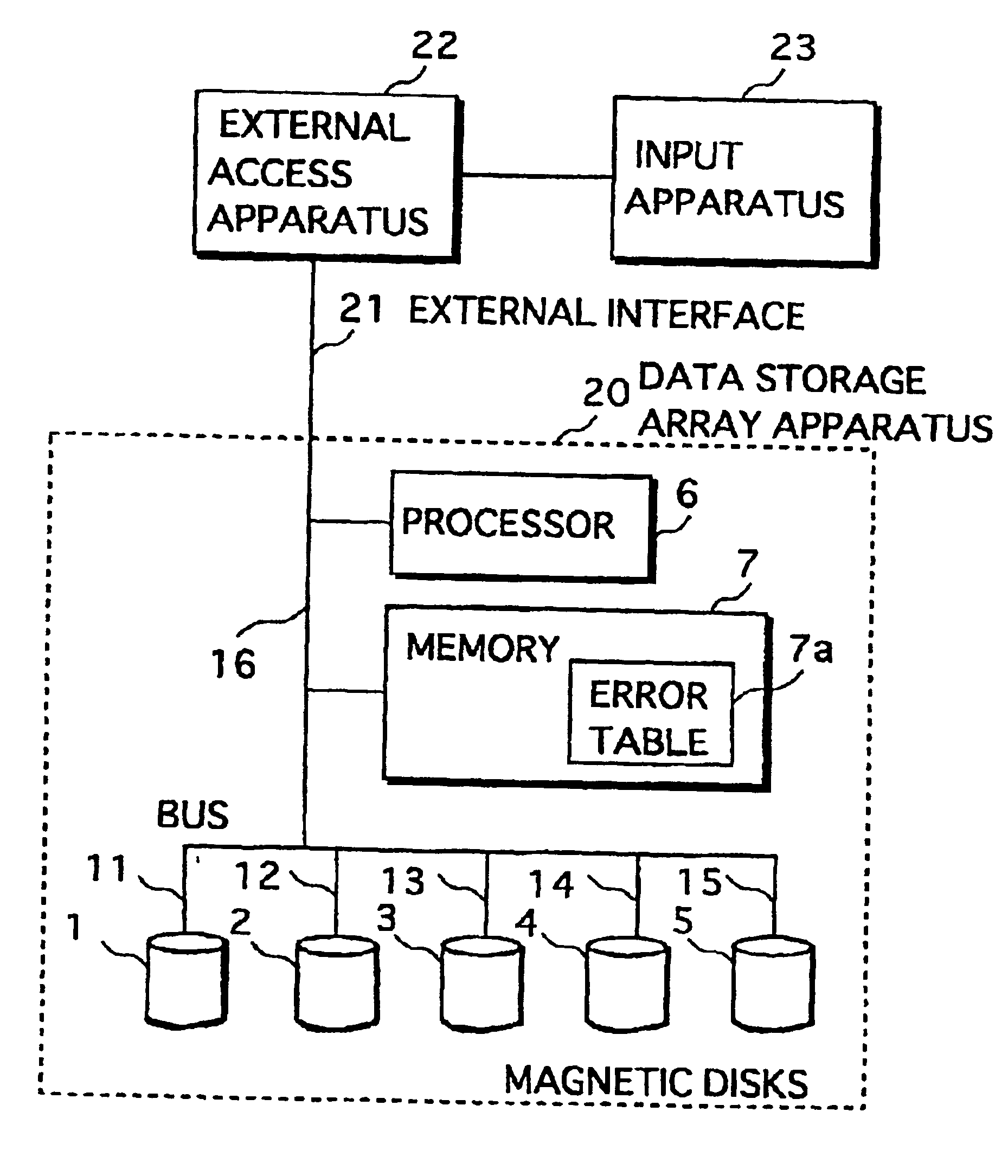
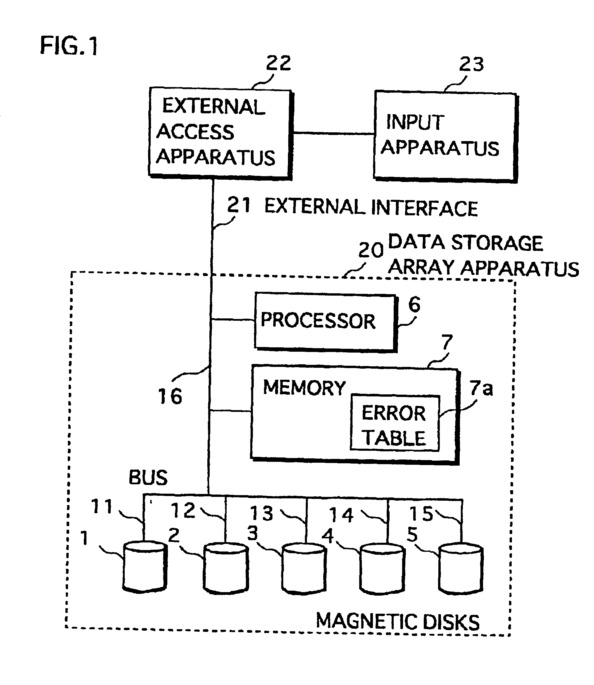
FIG. 1 shows the construction of a data storage system according to the first embodiment of the invention. The data storage system includes an external access apparatus 22, an input apparatus 23, and a data storage array apparatus 20 (hereafter abbreviated as “array apparatus”).

The external access apparatus 22 issues a write request to the array apparatus 20 in accordance with the data inputted by the input apparatus 23. The external access apparatus 20 also issues a read request to the array apparatus 20 and outputs the read data to the other apparatus (not shown).

The input apparatus 23 is a Digital Video (DV) camera for broadcasting, for example. The input apparatus 23 outputs video data, such as DV data, as the material data of the broadcasting program to the external access apparatus 22.

When receiving an access request (i.e., a write / read request) from the external access apparatus 22, the array apparatus 20 performs the requested write / read operation to the internal disk array....

embodiment 2

FIG. 5 shows the construction of a data storage system including an array apparatus according to the second embodiment of the invention. Compared with the construction of the array apparatus 50 shown in FIG. 1, the array apparatus shown in FIG. 5 has a processor 56 and memory 57 instead of the processor 6 and the memory 7, respectively, and a flash memory 58 newly added. The construction elements with the same reference numerals as in FIG. 1 function in the same manner, and so the following description omits their explanation but focuses on different points.

Compared with the processor 6, the processor 56 has added functions for writing the bit map data in the flash memory 58 by executing a program stored in the memory 57 and checking the bit map data written in the flash memory 58 immediately after the power is turned ON (at the starting of the system) and the system is reset. The processor 56 functions in the same manner as the processor 6 except for such added functions.

The memory...

embodiment 3

While the bit map data with the same content as in the parity group 200p (hereafter called “first bit map data”) is stored in the flash memory in the array apparatus according to the above second embodiment, second bit map data is stored in the flash memory 58 in this third embodiment. The second bit map data indicates the presence or absence of errors when the processor 56 writes bit map data (i.e., the first bit map data), which is stored in the error table, to the parity group 200p. The second bit map data contains a flag for each block making up of the parity group 200p.

Since the hardware construction of the data storage system in this embodiment is the same as in FIG. 5, the following description omits their explanation but focuses on different points.

FIG. 10 is a flow chart showing operations by the processor 56 for processing access requests from the outside of the apparatus. The procedures in this figure are different from those in FIG. 6 in that Steps 68a and 68b are inclu...


PUM


Abstract

A data storage array apparatus including multiple disks and writing / reading striped data and parity data onto / from the multiple disk devices, each having a storage area divided into multiple blocks, blocks across the multiple disks forming a group, the apparatus made up of: writing / reading means for writing / reading the striped data and the parity data in a group in accordance with an access request from the outside; error information generation means for generating error information indicating the presence / absence of an error caused by a writing operation by the writing / reading means and storing the error information in a memory; judgement means for, at each writing operation, judging whether the error information should be written to a predetermined group; and control means for controlling the writing / reading means to read error information from the memory and write the error information to the predetermined group according to a result obtained from the judgement means.

Description

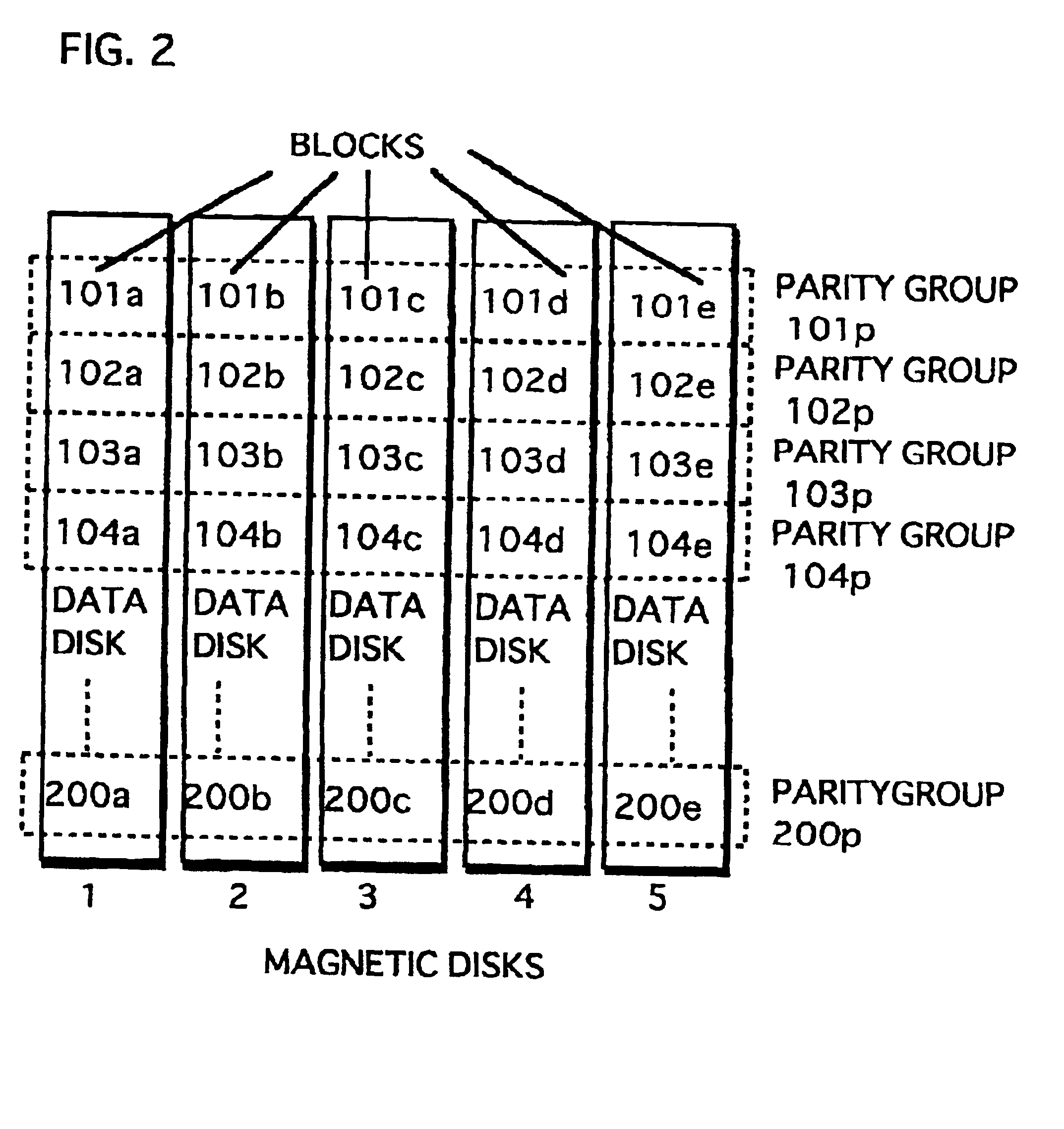
BACKGROUND OF THE INVENTION(1) Field of the InventionThe present invention relates to a data storage array apparatus consisting of multiple data storage devices and provided with redundant data to improve reliability.(2) Description of the Related ArtConventionally, data storage array apparatuses (hereafter abbreviated as “array apparatus”) are used for increasing speed for data access and improving reliability by distributing data with redundancy over multiple hard disks.The array apparatuses are well-known as Redundant Array of Inexpensive Disks (RAID). In the RAID-3, for instance, the storage area of each hard disk is divided into a plurality of blocks. Data is divided using the striping method and recorded onto the plurality of blocks, each of which forms a group together with corresponding blocks in the other hard disks including one that is exclusively used for storing parity data. The parity data is normally generated by carrying out the Exclusive-OR between the data blocks o...

Claims


Application Information

Patent Timeline
Patent Type & Authority Patents(United States)
IPC IPC(8): G06F11/10G06F11/00G06F11/07
CPCG06F11/0727G06F11/1076G06F11/0787G06F11/076G06F2211/104G06F2211/1016
Inventor FURUYA, SHINJIMIGITA, MANABU
Owner PANASONIC CORP
Learn More