Driving control method and circuit thereof

A technology for driving circuits and control circuits, applied in control/regulating systems, electrical components, regulating electrical variables, etc., can solve the problems of short-term conduction and continuous conduction of power devices, inseparable rise and charging, etc., to reduce the inductance and volume, reducing the excitation time, the effect of accelerated turn-off

Active Publication Date: 2020-09-11
MORNSUN GUANGZHOU SCI & TECH
View PDF12 Cites 9 Cited by
  • Summary
  • Abstract
  • Description
  • Claims
  • Application Information

AI Technical Summary

Problems solved by technology

[0007] With the continuous development of switching power supply technology, the requirements for its cost and volume are becoming more and more stringent. The reduction in volume is inseparable from the increase in frequency, and the reduction in cost is closely related to the reduction in devices. In order to cope with the increase in frequency The loss increases and the number of switching power supplies is reduced. Multi-mode switching circuit structures and more complex soft-switching control strategies are constantly being proposed. In multi-mode switching power supplies and complex control strategies, the power circuit adjusts the working state according to different working conditions. Under different working conditions, the power device will be turned on briefly and continuously. Usually, a resistor of about 10k will be connected between the gate and the source of the power switch tube, resulting in the publication number CN110311572A " A Transformer Isolation Drive Control Method and Its Isolation Drive Circuit" The scheme in the patent application cannot achieve continuous conduction
The bootstrap solution in the existing solutions mainly relies on the conduction of the lower tube to supplement energy for the bootstrap capacitor. Therefore, when the upper tube needs to be continuously turned on, the lower tube must be continuously turned off and cannot charge the bootstrap capacitor. The bootstrap capacitor can't keep the upper tube continuously turned on
Existing transformer isolation schemes rely on transformers to transmit switching signals. As we all know, transformers can only transmit AC signals, but cannot transmit DC signals. Therefore, when the drive needs to be continuously turned on, the transformer isolation scheme cannot continuously provide the voltage and energy required for turning on.
In summary, the other two power device drive solutions cannot achieve continuous conduction of power devices

Method used


Image

  • Driving control method and circuit thereof
  • Driving control method and circuit thereof
  • Driving control method and circuit thereof

Examples


Embodiment Construction

[0045] In order to better understand the design of the control circuit of the present invention, a specific embodiment of the present invention will now be described in detail with reference to the accompanying drawings.

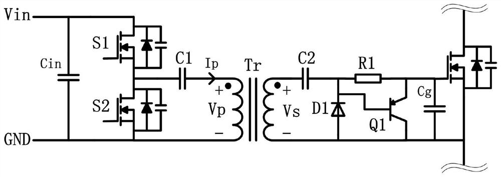
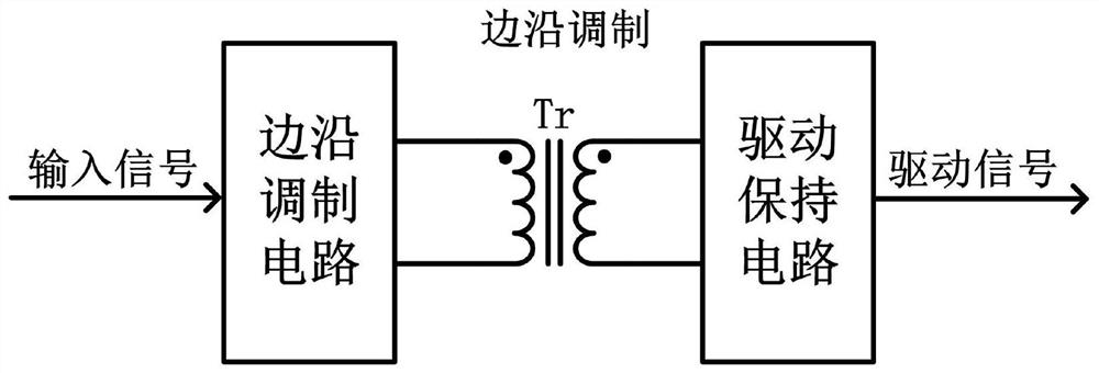
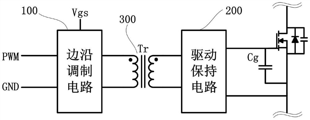
[0046] refer to figure 2 and image 3 , is a schematic diagram of the working principle and main structure of an isolated drive circuit of the present invention, including an edge modulation circuit 100 , an isolation transformer 300 and a drive hold circuit 200 . refer to Figure 4 , is the main waveform diagram of an isolated drive circuit of the present invention when it works, the edge modulation circuit 100 is used to receive the input signal and modulate its rising edge into a positive narrow pulse, and modulate its falling edge into a negative narrow pulse, and When the input signal is at a continuous high level, multiple continuous positive pulses are generated with a certain period, and the period is adjustable; the isolation transformer 300 is u...


PUM


Abstract

The invention discloses a driving control method and a circuit thereof. A rising edge of an input signal is modulated into a positive pulse with a fixed pulse width through an edge modulation circuit,a falling edge of the input signal is modulated into a negative pulse with a fixed pulse width, a plurality of continuous positive pulses are generated at a certain period in a state that the input signal is at a continuous high level, and the period is adjustable; positive and negative pulses generated by the edge modulation circuit are transmitted to the secondary side from the primary side inan isolation mode through the isolation transformer; a first positive pulse generated by the secondary side of the isolation transformer is demodulated into a rising edge of a driving signal through adriving holding circuit; a plurality of continuous positive pulses generated by the secondary side of the isolation transformer are demodulated to continuously supplement energy to the driven power tube so as to maintain the driving voltage, and negative pulses generated by the secondary side of the isolation transformer are demodulated to the falling edge of the driving signal so as to restore the input signal. The driving control method and the circuit thereof can achieve the purpose of isolation drive and have a normally open function of keeping continuous conduction of the MOS transistor.

Description

technical field [0001] The invention relates to the technical field of switching power supplies, in particular to a driving control method and circuit for a power switching device capable of realizing continuous conduction using transformer isolation. Background technique [0002] Compared with linear power supplies, switching power supplies have the characteristics of small size, high efficiency, and high power. They are widely used in the fields of automobiles, photovoltaics, industrial control, medical and handheld devices. It has superior performance at high frequencies, so it is used as a power switching device in the switching power supply. This type of device has a capacitor gate-controlled input terminal and is a voltage-controlled power semiconductor. Usually, a certain voltage is added to the gate and source. voltage, it can be turned on, and zero voltage or a certain negative voltage can be applied to turn it off. [0003] Switching power supplies have different ...

Claims


Application Information

Patent Timeline
Patent Type & Authority Applications(China)
IPC IPC(8): H02M3/335
CPCH02M3/33523H02M3/33576
Inventor 周瑜刘少雄薛泽宇
Owner MORNSUN GUANGZHOU SCI & TECH
Why Eureka
Try Eureka